
Page 406 - Pipeline Pigging Technology
P. 406
Pigging through Y fittings
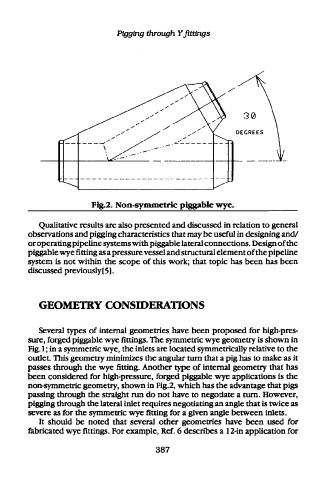
Fig.2. Non-symmetric piggable wye.
Qualitative results are also presented and discussed in relation to general
observations and pigging characteristics that may be useful in designing and/
or operating pipeline systems with piggable lateral connections. Design of the
piggable wye fitting as a pressure vessel and structural element of the pipeline
system is not within the scope of this work; that topic has been has been
discussed previously[5].
GEOMETRY CONSIDERATIONS
Several types of internal geometries have been proposed for high-pres-
sure, forged piggable wye fittings. The symmetric wye geometry is shown in
Fig. 1; in a symmetric wye, the inlets are located symmetrically relative to the
outlet. This geometry minimizes the angular turn that a pig has to make as it
passes through the wye fitting. Another type of internal geometry that has
been considered for high-pressure, forged piggable wye applications is the
non-symmetric geometry, shown in Fig.2, which has the advantage that pigs
passing through the straight run do not have to negotiate a turn. However,
pigging through the lateral inlet requires negotiating an angle that is twice as
severe as for the symmetric wye fitting for a given angle between inlets.
It should be noted that several other geometries have been used for
fabricated wye fittings. For example, Ref. 6 describes a 12-in application for
387