
Page 84 - Pipeline Rules of Thumb Handbook
P. 84
Construction 71
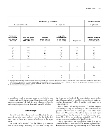
Defect caused by outside force Construction defect
In seam or other weld In body of pipe In girth weld
Plain dent or Gouge (Also
gouge-in-dent, Plain dent, gouge Plain dent Including gouges Undercut, Incomplete,
SAW Seam or or gouge-in-dent greater than 2% in SAW seams fusion Incomplete
Girth weld ERW or FW seam of pipe diameter or girth welds) Gouge-in-dent penetration, Crack
...... ...... ...... ...... ...... ......
X ...... X ...... X ......
...... ...... ...... X ...... X (f)
X ...... X ...... X ......
X (b) X (b) X (b) X (b) X (b) X (b,f)
...... ...... ...... X (b) ...... X (c)
X X X X X X
...... ...... ..... X (e) ...... ......
...... ...... ...... ...... ...... ......
...... ...... ...... ...... ...... X (f)
...... ...... ...... ...... ...... X (b,f)
...... ...... ...... ...... ...... X
X X X X X X (f)
X X X X X X
(g) One method of protecting hard spots from hydrogen stress cracking which, so far, has proven adequate is that of using a concentric band of sheet metal spaced away from the pipe by rubber
seals. The annular space is filled with coal tar to exclude ground water, and the metal band (which is itself coated) shields the hard spot from hydrogen-generating cathodic protection current.
The role of this band is merely to shield the pipe from the cathodic protection and not to strengthen the pipe.
(h) Use of low hydrogen electrodes is recommended.
a special shape such as a central hump to avoid interference input; nature and state of the pressurization media in the
with the girth weld reinforcement. Only sleeves with welded pipe. Consequently, it is possible to prescribe safe limits for
ends are recommended. Such sleeves tend to strengthen the avoiding burn-through while depositing weld metal on a
defective girth joint, whereas those with nonweld ends do not. defect (Table 2).
Table 2 shows a relationship between I.D. surface temper-
ature during welding and remaining wall thickness for various
Burn-through pressure and flow rates of natural gas. These values were
taken from AGA curves. The table is based on: heat input
3
1
Burn-through into a live pipeline would defeat the pur- characteristics of the / 32 -inch or / 8 -inch low hydrogen elec-
pose of a repair, would probably cause the line to be shut trode; 80 to 100 amps welding current at 20 volts DC; an
down, and might create a serious safety hazard to the repair average electrode travel speed of 4 to 5in./min.
crew. Energy input should not exceed these limits. Low hydro-
An AGA study revealed that the following parameters gen electrodes are recommended for reasons explained later.
control burn-through: remaining wall-thickness; welding heat Under these conditions, repairs can safely be made in the flat,