
Page 126 - Pipelines and Risers
P. 126
Finite Element Analysis of In-situ Behavior 99
As a result of this it was decided to make a simplified model of the installation. The model
may include the possibility of applying lay tension, and, to specify the lay angel between the
pipeline and the seabed to ensure good modeling of the contact forces in the touchdown zone
as the pipeline lands on the seabed (Figure 7.1).
As the pipeline stretches out, a stable equilibrium between the pipeline and the seabed must
be ensured. This requires a representative pipe/soil interaction model to be present. The
pipekoil interaction model will typically consist of a friction and a seabed stiffness definition.
It was realized that the seabed stiffness formulation must be able to describe several
pressure/penetration relationships, and that an anisotropic friction model may be used to
represent the difference in frictional resistance in the longitudinal and lateral directions of the
pipe.
Filling and draining of the pipeline
The filling and draining of the pipeline results in changes in the pipe weight and thus changes
in the pipeline configuration. The friction force between the pipeline and the seabed is a
function of the ground pressure and thus increases when the pipeline is filled.
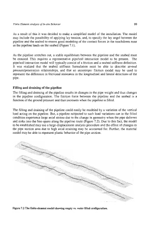
The filling and draining of the pipeline could easily be modeled by a variation of the vertical
load acting on the pipeline. But, a pipeline subjected to such load variations can in the filled
condition experience large axial strains due to the change in geometry when the pipe deforms
and sinks into the free-spans along the pipeline route (Figure 7.2). Due to this fact, the model
to be established may use a large-displacement analysis procedure and the effect of changes in
the pipe section area due to high axial straining may be accounted for. Further, the material
model may be able to represent plastic behavior of the pipe section.
Figure 7.2 The finite-element model showing empty vs. water filled configuration.