
Page 132 - Pipelines and Risers
P. 132
Finite Element Analysis of In-situ Behavior 105
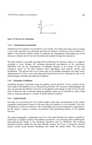
Figure 7.8 Stresdstrain relationship.
7.5.2 Geometrical non-linearity
Geometrical non-linearity is accounted for in the model. This means that strains due to change
in the model geometry are calculated and that this stiffness contribution (strcss stiffness) is
added to the structure stiffness matrix. In addition, the instantaneous (deformed) state of the
structure is always used in the next increment and updated through the calculation.
The latter feature is especially important when performing the dynamic analysis of a pipeline
subjected to wave loading. By including geometrical non-linearity in the calculation,
ABAQUS will use the instantaneous co-ordinates (instead of the initial) of the load
integration points on the pipe elements when calculating water particle velocity and
acceleration. This ensures that even if some parts of the pipeline undergoes very large lateral
displacements (15-20 m.), the correct drag and inertia forces will be calculated on each of the
individual pipe elements that make up the pipeline.
7.5.3 Boundary Conditions
Arbitrarily boundary conditions along the pipeline can be specified. If only a section of the
total length of the pipeline is to be analyzed (e.g. between two successive rockdumpings), the
user can simulate the stiffness of the rest of the pipeline with springs in each of the two pipe
ends. If there are other constraints along the pipeline, these can be modeled by either fixing
nodes or assigning springs to a number of nodes along the pipeline.
7.5.4 Seabed Model
The basis for constructing the 3-D seabed model is data from measurements of the seabed
topography (bathymetric surveys) in the area where the pipeline is to be installed. From this
information a corridor of width up to 40 m and lengths up to several kilometers is generated in
the FE model to ensure a realistic environment when performing analysis of the pipeline
behavior.
The seabed topography is represented with four node rigid elements that makes it possible to
model flat or complex surfaces with arbitrary geometries. An advantage when modeling the
three-dimensional seabed is the smoothing algorithm used by ABAQUS. The resulting
smoothed surfaces, unlike the flat rigid element surfaces will have a continuous outward
surface notmal across element boundaries and model the seabed better. The smoothed