
Page 104 - Planning and Design of Airports
P. 104
74 Airp o r t Pl anning
Aircraft navigating a route at altitude operate in precisely the
same manner. A heading is calculated, based on the speed and direc-
tion of the wind, and the speed of the aircraft itself, that will give the
aircraft the desired track. The angle between the desired track and the
calculated heading is known as the crab angle. The magnitude of this
angle can be obtained from the following relation:
V
sin x = c (2-3)
V
h
where V is the crosswind in miles per hour or knots and V is the true
c h
airspeed in miles per hour or knots.
The crosswind, V , is defined as the component of the wind, V ,
c w
that is at a right angle to the track. The angle x is referred to as the crab
angle. It will be noted that the magnitude of the angle is directly pro-
portional to the speed of the wind and inversely proportional to the
speed of the aircraft.
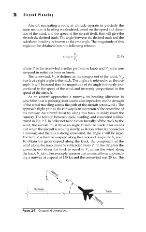
As an aircraft approaches a runway, its heading (direction in
which the nose is pointing) is of course also dependent on the strength
of the wind traveling across the path of the aircraft (crosswind). The
approach flight path to the runway is an extension of the centerline of
the runway. An aircraft must fly along this track to safely reach the
runway. The relation between track, heading, and crosswind is illus-
trated in Fig. 2-7. In order not to be blown laterally off the track by the
wind, the aircraft must fly at an angle x from the track. This means
that when the aircraft is moving slowly, as it does when it approaches
a runway, and there is a strong crosswind, the angle x will be large.
The term V is the true airspeed along the track and is equal to V cos x.
t h
To obtain the groundspeed along the track, the component of the
wind along the track must be subtracted from V . In the diagram the
t
groundspeed along the track is equal to V minus the wind along
t
the track, V sin x. For example, assume that an aircraft was approach-
w
ing a runway at a speed of 135 kn and the crosswind was 25 kn. The
V c (Wind) V w V h
x
Runway
Track
V t Heading
FIGURE 2-7 Crosswind correction.