
Page 154 - Planning and Design of Airports
P. 154
122 Airp o r t Pl anning
The localizer consists of an antenna, which is located on the exten-
sion of the runway centerline approximately 1000 ft from the far end
of the runway, and a localizer transmitter building located about 300 ft
to one side of the runway at the same distance from the end of the
runway as the antenna. The glide slope facility is placed 750 to 1250 ft
down the runway from the threshold and is located to one side of the
runway centerline at a distance which can vary from 400 to 650 ft. The
functioning of the localizer and the glide slope facility is affected by
the close proximity of moving objects such as vehicular and aircraft
traffic. During inclement weather the use of the ILS critical areas
inhibit aircraft and vehicles from entering into areas that would
impede an aircraft inside of the outer marker from receiving a clear
signal. Stationary objects nearby can also cause a deterioration of sig-
nals. Abrupt changes of slope in proximity of the antennas are not
permitted or the signal will not be transmitted properly. Another lim-
itation of the ILS is that the glide slope beam is not reliable below a
height of about 200 ft above the runway.
As with VOR and NDB systems, the localizer and glide slope
components of the ILS are highly sensitive to their proximity to sur-
rounding objects that may interfere with their radio signals. As such,
there are specific restrictions to construction in the immediate vicin-
ity of these systems.
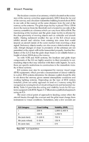
ILS systems may also be accompanied by runway visual range
(RVR) equipment, which provide a measurement of lateral visibility
to a pilot. RVR systems determine the distance a pilot should be able
to see down the runway, given current atmospheric conditions and
existing lighting systems. Depending on the type of RVR system
installed, pilots can safely approach to land on a runway using ILS
navigation in varying levels of cloud ceiling levels and horizontal vis-
ibility. Table 3-3 provides the ceiling and visibility levels for ILS sys-
tems equipped with RVR. Figure 3-17 illustrates a published approach
using an ILS.
The most critical point of approach to landing comes when the
aircraft breaks through the overcast and the pilot must change from
instrument to visual conditions. Sometimes, only a few seconds are
ILS Category Cloud Ceiling Visibility (RVR)
I 200 ft 1,800–2,400 ft
II 100 ft 1,200 ft
IIIa (auto land) 0–100 ft 700 ft
IIIb (auto rollout) 0–50 ft 150 ft
IIIc (auto taxi) 0 ft 0 ft
TABLE 3-3 ILS Capabilities