
Page 320 - Planning and Design of Airports
P. 320
278 Airp o r t D e sign
Isolation joint
Detail 1
Non-extruding premolded compressible material
T
3/4" (19 mm) Te
To the nearest joint but
Te = 1.25 T to nearest 1" (3 mm)
not less than 10" (3 m) but at least T + 2" (5 mm)
Type A thickened edge
Contraction joints
Detail 2 Detail 2
T/2 ± d/2 T/2 ± d/2
T T
Tie bar 30" (76 cm) long on 30" (76 cm) centers Paint and oil one end of dowel
Type B hinged Detail 2 Type C doweled
T
Type D dummy
Construction joint
Detail 3
T/2 ± d/2
T
Paint and oil one end of dowel
Type E doweled
NOTE:
1. Shaded area is joint sealant.
2. Groove must be formed by sawing.
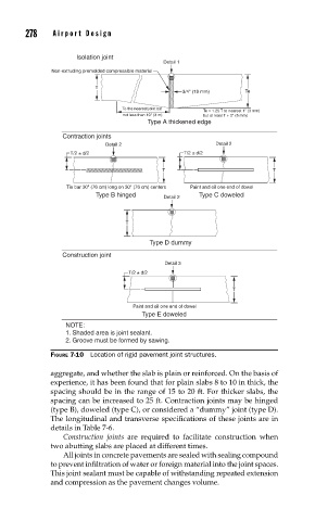
FIGURE 7-10 Location of rigid pavement joint structures.
aggregate, and whether the slab is plain or reinforced. On the basis of
experience, it has been found that for plain slabs 8 to 10 in thick, the
spacing should be in the range of 15 to 20 ft. For thicker slabs, the
spacing can be increased to 25 ft. Contraction joints may be hinged
(type B), doweled (type C), or considered a “dummy” joint (type D).
The longitudinal and transverse specifications of these joints are in
details in Table 7-6.
Construction joints are required to facilitate construction when
two abutting slabs are placed at different times.
All joints in concrete pavements are sealed with sealing compound
to prevent infiltration of water or foreign material into the joint spaces.
This joint sealant must be capable of withstanding repeated extension
and compression as the pavement changes volume.