
Page 315 - Planning and Design of Airports
P. 315
Structural Design of Airport Pavements 273
CBR
3 4 5 6 7 89 10 15 20 30 40 50
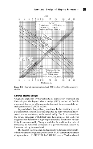
B– 767
Contact area = 202.46 sq. in.
Dual spacing = 45 in.
Tandem spacing = 56.00 in.
Gross aircraft
weight, LB
325,000
300,000
1 in. = 25.4 mm 150,000 200,000
1 lb. = 0.454 kg
Annual departures 6,000 1,200 Thickness hot mix
3,000
Asphalt surfaces
15,000
25,000 4–in. Critical areas
3–in. Noncritical areas
3 4 5 6 7 89 10 15 20 30 40 50
Thickness, in.
FIGURE 7-5 Example approximation chart, CBR method of fl exible pavement
design.
Layered Elastic Design
Originally applied in 1995 specifically for the heaviest of aircraft, the
FAA adopted the layered elastic design (LED) method of flexible
pavement design for all pavements designed to accommodate air-
craft greater than 30,000 lb in 2008.
Layered elastic design theory considers the fact that the layers of
pavement that support loads are impacted by both vertical and hori-
zontal strains and stress, as illustrated in Fig. 7-6. To accommodate
the strain, pavement will deflect with the passing of the load. The
magnitude of deflection of a given pavement is a function of its elas-
ticity, E, as measured by Young’s modulus. In addition, the ratio of
transverse to horizontal deflection of a pavement layer, known as
Poisson’s ratio, μ, is considered.
The layered elastic design and cumulative damage failure meth-
ods of pavement design are applied in the FAA’s computer pavement
design software, FAARFIELD. FAARFIELD uses a Windows-based