
Page 354 - Planning and Design of Airports
P. 354
310 Airp o r t D e sign
NOTES:
PARALLEL TO AIMING ANGLE 1. THE OPTIMUM LOCATION FOR EACH LIGHT UNIT
RUNWAY CENTERLINE 15° IS IN LINE WITH THE RUNWAY THRESHOLD AT 40 FT
FROM THE RUNWAY EDGE.
2. A 90 FT UPWIND AND A 40 FT DOWNWIND
40°
90°
LONGITUDINAL TOLERANCE IS PERMITTED FROM THE
RUNWAY THRESHOLD IN LOCATING THE LIGHT UNITS.
3. THE LIGHT UNITS SHALL BE EQUALLY SPACED
40° (+35, –0)
FROM THE RUNWAY CENTERLINE. WHEN
ADJUSTMENTS ARE NECESSARY THE DIFFERENCE IN
THE DISTANCE OF THE UNITS FROM THE RUNWAY
CENTERLINE SHALL NOT EXCEED 10 FT.
4. THE BEAM CENTERLINE (AIMING ANGLE) OF EACH
RUNWAY LIGHT UNIT IS AIMED 15 DEGREES OUTWARD FROM A
CENTERLINE
LINE PARALLEL TO THE RUNWAY CENTERLINE AND
INCLINED AT AN ANGLE 10 DEGREES ABOVE THE
HORIZONTAL, IF ANGLE ADJUSTMENTS ARE
NECESSARY, PROVIDE AN OPTICAL BAFFLE AND
CHANGE THE ANGLES TO 10 DEGREES HORIZONTAL
AND 20 DEGREES VERTICAL.
RUNWAY THRESHOLD
5. LOCATE THE ADL EQUIPMENT A MINIMUM
DISTANCE OF 40 FT FROM OTHER RUNWAYS AND
TAXIWAYS.
6. IF REILS ARE USED WITH PAPI. INSTALL REILS
AT 75 FT FROM THE RUNWAY EDGE. WHEN
THRESHOLD LIGHTS (REF)
INSTALLED WITH OTHER FACILITIES REILS SHALL
40°
TAXIWAY 15° BE INSTALLED AT 40 FT FROM THE RUNWAY EDGE.
40° (+35, –0)
OR AIMING ANGLE 7. THE ELEVATION OF BOTH UNITS SHALL BE
RUNWAY WITHIN 3 FT OF THE HORIZONTAL PLANE THROUGH
THE RUNWAY CENTERLINE.
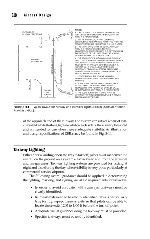
FIGURE 8-14 Typical layout for runway end identifi er lights (REILs) (Federal Aviation
Administration).
of the approach end of the runway. The system consists of a pair of syn-
chronized white flashing lights located on each side of the runway threshold
and is intended for use when there is adequate visibility. An illustration
and design specifications of REILs may be found in Fig. 8-14.
Taxiway Lighting
Either after a landing or on the way to takeoff, pilots must maneuver the
aircraft on the ground on a system of taxiways to and from the terminal
and hangar areas. Taxiway lighting systems are provided for taxiing at
night and also during the day when visibility is very poor, particularly at
commercial service airports.
The following overall guidance should be applied in determining
the lighting, marking, and signing visual aid requirements for taxiways:
• In order to avoid confusion with runways, taxiways must be
clearly identified.
• Runway exits need to be readily identified. This is particularly
true for high-speed runway exits so that pilots can be able to
locate these exits 1200 to 1500 ft before the turnoff point.
• Adequate visual guidance along the taxiway must be provided.
• Specific taxiways must be readily identified.