
Page 355 - Planning and Design of Airports
P. 355
Airport Lighting, Marking, and Signage 311
• The intersections between taxiways, the intersections between
runways and taxiways, and runway-taxiway crossings need
to be clearly marked.
• The complete taxiway route from the runway to the apron
and from the apron to the runway should be easily identified.
There are two primary types of lights used for the designation of
taxiways. One type delineates the edges of taxiways [21] and the
other type delineates the centerline of the taxiway [27]. In addition,
there is an increasing use of lighting systems on taxiways, such as
runway guard lights (RGLs) and stop bars, to identify intersections
with runways, in an effort to reduce accidental incursions on to active
runway environments.
Taxiway Edge Lights
Taxiway edge lights are elevated blue colored bidirectional lights usu-
ally located at intervals of not more than 200 ft on either side of the
taxiway. The exact spacing is influenced by the physical layout of the
taxiways. Straight sections of taxiways generally require edge light
spacing in 200-ft intervals, or at least three lights equally spaced for
taxiway straight line sections less than 200 ft in length.
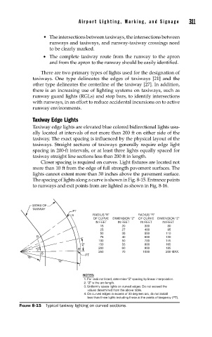
Closer spacing is required on curves. Light fixtures are located not
more than 10 ft from the edge of full strength pavement surfaces. The
lights cannot extent more than 30 inches above the pavement surface.
The spacing of lights along a curve is shown in Fig. 8-15. Entrance points
to runways and exit points from are lighted as shown in Fig. 8-16.
SIDES OF
TAXIWAY
PT
B RADIUS “R” RADIUS “R”
OF CURVE DIMENSION “Z” OF CURVE DIMENSION “Z”
IN FEET IN FEET IN FEET IN FEET
15 20 300 80
25 27 400 95
50 35 500 110
B 75 40 600 130
100 50 700 145
“Z” 150 55 800 165
900
“Z” B 200 60 1000 185
200 MAX.
70
250
B
PT
“R”
“R”
NOTES:
1. For radii not listed, determine “Z” spacing by linear interpolation.
2. “Z” is the arc length.
3. Uniformly space lights on curved edges. Do not exceed the
values determined from the above table.
4. On curved edges in excess of 30 degrees arc, do not install
less than three lights including those at the points of tangency (PT).
FIGURE 8-15 Typical taxiway lighting on curved sections.