Page 144 - Plastics Engineering
P. 144

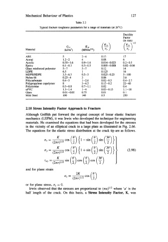
Mechanical Behaviour of Plastics                                127

                                               Table 2.2
                         spital fracture toughness parameters for a range of  materials (at 20°C)
                                                                           Ductility
                                                                           Factor
                                                    KI~  (5)               (in mm)
                                         GI,                               ($)'I2
                 Material               (kJ/mz)   (m/m3I2)
                 ABS                   5          2-4         0.13         17
                 Acetal                1.2-2      4           0.08         6
                 Acrylic               0.35-1.6   0.9-1.6     0.014-0.023   0.2-0.5
                 EPOXY                 0.1 -0.3   0.3-0.5     0.005-0.008   0.02-0.06
                 Glass reinforced polyester   5-7   5-7       0.12         14
                 LDPE                  6.5        1           0.125        16
                 MDPEMDPE              3.5-6.5    0.5-5       0.025-0.25   5-100
                 Nylon 66              0.25-4     3           0.06         3.6
                 Polycarbonate         0.4-5      1-2.6       0.02-0.5     0.4-2.7
                 Polypropylene copolymer   8      3-4.5       0.15-0.2     22-40
                 Polystyrene           0.3-0.8    0.7-1.1     0.02         0.4
                 UPVC                  1.3-1.4    1-4         0.03-0.13    1.1-18
                 Glass                 0.01  -0.02   0.75     0.01         0.1
                 Mild Steel            100        140         0.5          250


                 2.18 Stress Intensity Factor Approach to Fracture
                 Although Griffith put  forward the  original concept of  linear elastic fracture
                mechanics (LEFM), it was Irwin who developed the technique for engineering
                 materials. He examined the equations that had been developed for the stresses
                 in the vicinity of  an elliptical crack in a large plate as illustrated in Fig. 2.66.
                The equations for the elastic stress distribution at the crack tip are as follows.
                                        cos (f) { 1 -sin  (f) sin (y)}
                            B  --
                              - (2nr)l/2
                                   K    cos (4)  { 1 + sin (:)  sin (  ) }
                            By = -
                                 (2nr) 112

                            txy =-      sin (!)  cos (i) cos ( y)
                                 (2nr) 1 12
                 and for plane strain
                                                        fH\
                                        u --        cos (2)
                                          - (2Irr)1/2
                 or for plane stress, a, = 0.
                   Irwin observed that the stresses are proportional to (nu)'/2 where  'u' is the
                 half  length of  the  crack. On  this  basis,  a  Stress Intensity Factor,  K,  was
   139   140   141   142   143   144   145   146   147   148   149