
Page 201 - Plastics Engineering
P. 201
184 Mechanical Behaviour of Composites
Using matrix notation, equation (3.20) may be transposed to give the stresses
as a function of the strains
I4 = [s1-1{4
This may also be written as
(3.21)
where [Q] is the stifless matrix and its terms will be
El E2
Qii = Q22 = Q&=G12
1 - W2Y1 1 - YIV12
(ii) Loading off the Fibre Axis
The previous analysis is a preparation for the more interesting and practical
situation where the applied loading axis does not coincide with the fibre axis.
This is illustrated in Fig. 3.10.
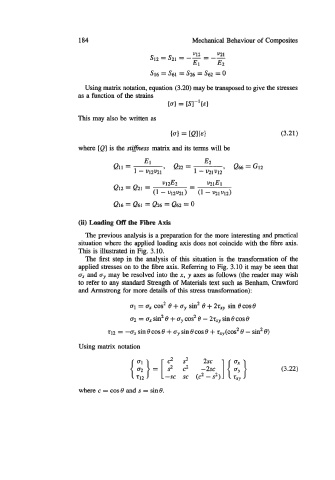
The first step in the analysis of this situation is the transformation of the
applied stresses on to the fibre axis. Refemng to Fig. 3.10 it may be seen that
a, and ay may be resolved into the x, y axes as follows (the reader may wish
to refer to any standard Strength of Materials text such as Benham, Crawford
and Armstrong for more details of this stress transformation):
01 = a, cos2 e + ay sin2 e + 2tXy sin ecose
a2 = a, sin2 e + ay cos2 e - 2rXy sin 8 cos 6
t12 = -a, sin e cos e + a,, sin e cos e + r,..(cos2 e - sin2 e)
Using matrix notation
{ i;}= sc (2 - 2) ] {2} (3.22)
c2 2
2sc
[
-sc 2 2
-2sc
where c = cos0 and s = sine.