
Page 119 - Polymer-based Nanocomposites for Energy and Environmental Applications
P. 119
Nanoclay and polymer-based nanocomposites: Materials for energy efficiency 95
Si
RO OR
O
RO OR c
Si
Si
g RO OR
a b OR
OR
e RO OR
f Si
d
Fig. 3.11 Schematic drawing of continuous extrusion process [97].
nozzle system situated between the plasticizing unit and the shutoff nozzle of an injec-
tion molder to introduce the gas into the polymer, while the University of Warwick
process incorporates the gas into the system by using a bolt-on gas injection port
[100]. Once the gas/polymer phase is injected into the mold, the pressure decreases
resulting in a thermodynamic instability in the system, thus causing the formation
of microcellular foam the process steps are summarized in Fig. 3.12.
The continuous extrusion must be designed to include a gas injection port and to
withstand large pressures within the barrel without gas losses [89], whereas these
requirements are needless in the semicontinuous process. The semicontinuous extru-
sion process was consisted with two basic steps [102]. First is to create a single-phase
mixture of gas and polymer, to given then enough time to reach equilibrium in the
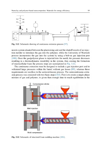
Compression stroke
Melt injection
Mold compression
Fig. 3.12 Schematic of structural foam molding machine [101].