
Page 586 - Polymer-based Nanocomposites for Energy and Environmental Applications
P. 586
Hybrid materials based on polymer nanocomposites for environmental applications 539
represents the main part of greenhouse gas emissions. Among users of electricity,
lighting represents a large part of energy consumption in buildings (residential, indus-
trial, and commercial activities). Approximately one-fifth of the total electricity pro-
duction in the world is devoted to the lighting [143]. However, incandescent light
bulbs and fluorescent lamps consume a large amount of electricity to light the build-
ings or houses and are not efficient in conversion of electricity into visible light. Most
of the consumed electricity by these devices is lost in heat, and recently, it is proposed
that the lighting technologies should look for an energy saving in device operation,
which in turn will reduce the gas emissions. In this optic, the use of hybrid materials
may be potentially interesting for a large energy saving in solid-state lighting field.
The devices we present here are essentially improved OLEDs by modifying the emit-
ter materials with incorporation of inorganic components into the organic matrix.
Operating principle and performance of organic light emitting diodes
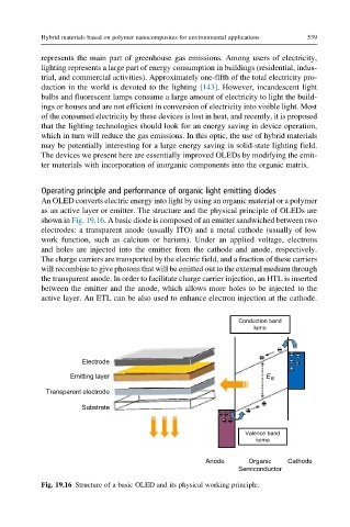
An OLED converts electric energy into light by using an organic material or a polymer
as an active layer or emitter. The structure and the physical principle of OLEDs are
shown in Fig. 19.16. A basic diode is composed of an emitter sandwiched between two
electrodes: a transparent anode (usually ITO) and a metal cathode (usually of low
work function, such as calcium or barium). Under an applied voltage, electrons
and holes are injected into the emitter from the cathode and anode, respectively.
The charge carriers are transported by the electric field, and a fraction of these carriers
will recombine to give photons that will be emitted out to the external medium through
the transparent anode. In order to facilitate charge carrier injection, an HTL is inserted
between the emitter and the anode, which allows more holes to be injected to the
active layer. An ETL can be also used to enhance electron injection at the cathode.
Conduction band
lumo
Electrode
Emitting layer E G
Transparent electrode
Substrate
Valence band
homo
Anode Organic Cathode
Semiconductor
Fig. 19.16 Structure of a basic OLED and its physical working principle.