
Page 15 - Power Electronic Control in Electrical Systems
P. 15
//SYS21/F:/PEC/REVISES_10-11-01/075065126-CH001.3D ± 7 ± [1±30/30] 17.11.2001 9:43AM
Power electronic control in electrical systems 7
a
d axis
θ
q axis
rotation
b c
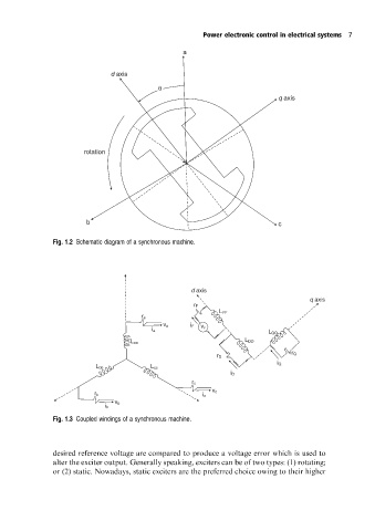
Fig. 1.2 Schematic diagram of a synchronous machine.
d axis
q axis
r F
L FF
r a
v a i F
v F
i a
L QQ
L DD
L aa
r Q
r D
i Q
L bb L cc
i D
r c
v c
r b
i c
v b
i b
Fig. 1.3 Coupled windings of a synchronous machine.
desired reference voltage are compared to produce a voltage error which is used to
alter the exciter output. Generally speaking, exciters can be of two types: (1) rotating;
or (2) static. Nowadays, static exciters are the preferred choice owing to their higher