
Page 16 - Power Electronic Control in Electrical Systems
P. 16
//SYS21/F:/PEC/REVISES_10-11-01/075065126-CH001.3D ± 8 ± [1±30/30] 17.11.2001 9:43AM
8 Electrical power systems ± an overview
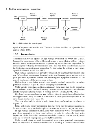
Fig. 1.4 Main controls of a generating unit.
speed of response and smaller size. They use thyristor rectifiers to adjust the field
current (Aree, 2000).
1.3.2 Transmission
Transmission networks operate at high voltage levels such as 400 kV and 275 kV,
because the transmission of large blocks of energy is more efficient at high voltages
(Weedy, 1987). Step-up transformers in generating substations are responsible for
increasing the voltage up to transmission levels and step-down transformers located
in distribution substations are responsible for decreasing the voltage to more man-
ageable levels such as 66 kV or 11 kV.
High-voltage transmission is carried by means of AC overhead transmission lines
and DC overhead transmission lines and cables. Ancillary equipment such as switch-
gear, protective equipment and reactive power support equipment is needed for the
correct functioning of the transmission system.
High-voltage transmission networks are usually `meshed' to provide redundant
paths for reliability. Figure 1.5 shows a simple power network.
Under certain operating conditions, redundant paths may give rise to circulating
power and extra losses. Flexible alternating current transmission systems controllers are
able to prevent circulating currents in meshed networks (IEEE/CIGRE, 1995).
Overhead transmission lines are used in high-voltage transmission and in distribu-
tion applications. They are built in double circuit, three-phase configuration in the
same tower, as shown in Figure 1.6.
They are also built in single circuit, three-phase configurations, as shown in
Figure 1.7.
Single and double circuit transmission lines may form busy transmission corridors.
In some cases as many as six three-phase circuits may be carried on just one tower.
In high-voltage transmission lines, each phase consists of two or four conductors
per phase, depending on their rated voltage, in order to reduce the total series
impedance of the line and to increase transmission capacity. One or two sky wires
are used for protection purposes against lightning strikes.
Underground cables are used in populated areas where overhead transmission
lines are impractical. Cables are manufactured in a variety of forms to serve different