
Page 169 - Power Electronic Control in Electrical Systems
P. 169
//SYS21/F:/PEC/REVISES_10-11-01/075065126-CH005.3D ± 157 ± [153±176/24] 17.11.2001 10:15AM
Power electronic control in electrical systems 157
An ideal thyristor exhibits infinite resistance to positive anode current unless a
positive current pulse I G is supplied through the gate. Then, the thyristor enters its on
state and its resistance becomes zero. It remains at this state till the anode current
becomes zero. If the gate current pulse I G is then zero, the thyristor resumes its initial
state of having infinite resistance from the anode to the cathode to positive anode
current. However, it should be noted that the anode current does not become zero
even when the gate pulse current I G becomes zero when the thyristor is on. This is the
most significant difference between the thyristor and the other fully controlled
semiconductors, which will be presented later in this chapter.
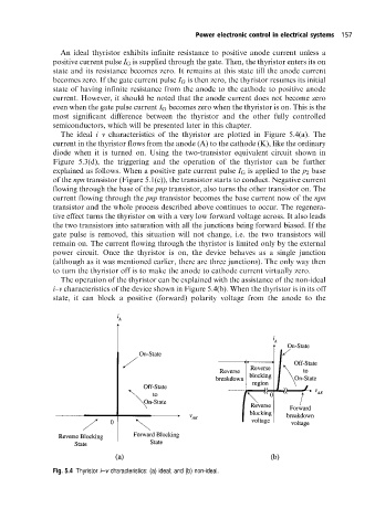
The ideal i±v characteristics of the thyristor are plotted in Figure 5.4(a). The
current in the thyristor flows from the anode (A) to the cathode (K), like the ordinary
diode when it is turned on. Using the two-transistor equivalent circuit shown in
Figure 5.3(d), the triggering and the operation of the thyristor can be further
explained as follows. When a positive gate current pulse I G is applied to the p 2 base
of the npn transistor (Figure 5.1(c)), the transistor starts to conduct. Negative current
flowing through the base of the pnp transistor, also turns the other transistor on. The
current flowing through the pnp transistor becomes the base current now of the npn
transistor and the whole process described above continues to occur. The regenera-
tive effect turns the thyristor on with a very low forward voltage across. It also leads
the two transistors into saturation with all the junctions being forward biased. If the
gate pulse is removed, this situation will not change, i.e. the two transistors will
remain on. The current flowing through the thyristor is limited only by the external
power circuit. Once the thyristor is on, the device behaves as a single junction
(although as it was mentioned earlier, there are three junctions). The only way then
to turn the thyristor off is to make the anode to cathode current virtually zero.
The operation of the thyristor can be explained with the assistance of the non-ideal
i±v characteristics of the device shown in Figure 5.4(b). When the thyristor is in its off
state, it can block a positive (forward) polarity voltage from the anode to the
Fig. 5.4 Thyristor i±v characteristics: (a) ideal; and (b) non-ideal.