
Page 33 - Power Electronic Control in Electrical Systems
P. 33
//SYS21/F:/PEC/REVISES_10-11-01/075065126-CH001.3D ± 23 ± [1±30/30] 17.11.2001 9:43AM
Power electronic control in electrical systems 23
1.08
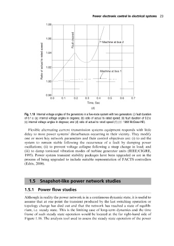
1.06 Fault cleared Machine at bus 2
Ratio of actual to rated speed 1.04 Machine at bus 1
1.02
1.00
0.98
0.0 0.1 0.2 0.3 0.4 0.5 0.6 0.7
Time, Sec
(d)
Fig. 1.18 Internal voltage angles of the generators in a five-node system with two generators: (i) fault duration
of 0.1 s: (a) internal voltage angles in degrees; (b) ratio of actual to rated speed; (ii) fault duration of 0.2 s:
(c) internal voltage angles in degrees; and (d) ratio of actual to rated speed (1) (# 1968 McGraw-Hill).
Flexible alternating current transmission systems equipment responds with little
delay to most power systems' disturbances occurring in their vicinity. They modify
one or more key network parameters and their control objectives are: (i) to aid the
system to remain stable following the occurrence of a fault by damping power
oscillations; (ii) to prevent voltage collapse following a steep change in load; and
(iii) to damp torsional vibration modes of turbine generator units (IEEE/CIGRE,
1995). Power system transient stability packages have been upgraded or are in the
process of being upgraded to include suitable representation of FACTS controllers
(Edris, 2000).
1.5 Snapshot-like power network studies
1.5.1 Power flow studies
Although in reality the power network is in a continuous dynamic state, it is useful to
assume that at one point the transient produced by the last switching operation or
topology change has died out and that the network has reached a state of equilib-
rium, i.e. steady state. This is the limiting case of long-term dynamics and the time
frame of such steady state operation would be located at the far right-hand side of
Figure 1.16. The analysis tool used to assess the steady state operation of the power