
Page 382 - Power Electronic Control in Electrical Systems
P. 382
//SYS21/F:/PEC/REVISES_10-11-01/075065126-CH008.3D ± 362 ± [290±372/83] 17.11.2001 10:29AM
362 Transient studies of FACTS and Custom Power equipment
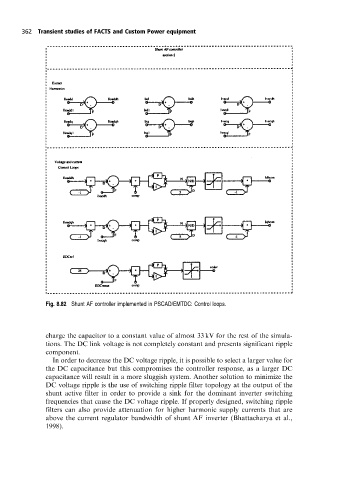
Fig. 8.82 Shunt AF controller implemented in PSCAD/EMTDC: Control loops.
charge the capacitor to a constant value of almost 33 kV for the rest of the simula-
tions. The DC link voltage is not completely constant and presents significant ripple
component.
In order to decrease the DC voltage ripple, it is possible to select a larger value for
the DC capacitance but this compromises the controller response, as a larger DC
capacitance will result in a more sluggish system. Another solution to minimize the
DC voltage ripple is the use of switching ripple filter topology at the output of the
shunt active filter in order to provide a sink for the dominant inverter switching
frequencies that cause the DC voltage ripple. If properly designed, switching ripple
filters can also provide attenuation for higher harmonic supply currents that are
above the current regulator bandwidth of shunt AF inverter (Bhattacharya et al.,
1998).