
Page 387 - Power Electronic Control in Electrical Systems
P. 387
//SYS21/F:/PEC/REVISES_10-11-01/075065126-CH008.3D ± 367 ± [290±372/83] 17.11.2001 10:29AM
Power electronic control in electrical systems 367
8.10 Solid-State Transfer Switch (SSTS)
The SSTS is a high-speed, open-transition switch that enables the transfer of elec-
trical loads from one AC power source to another within a few milliseconds. It is
designed to replace the mechanical auto-transfer equipment currently used to switch
major industrial and commercial facilities from one feeder to another. The open-
transition property of the SSTS means that the switch breaks contact with one source
before it makes contact with the other source.
The advantage of this transfer scheme over the closed-transition mechanical switch
is that the electrical sources are never cross-connected unintentionally. The cross
connection of independent AC sources, with the alternate source switching on to a
faulted system is discouraged by electrical utilities (Chan, Kara and Kieboom, 1998).
The SSTS can be used very effectively to protect sensitive loads against voltage sags,
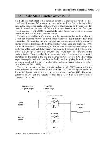
swells and other electrical disturbances. The basic configuration of this device con-
sists of two three-phase solid-state switches, one for the main feeder and one for the
backup feeder. These switches have an arrangement of back-to-back connected
thyristors, as illustrated in the one-line diagram shown in Figure 8.91. If a voltage
sag or interruption is detected on the main feeder that is supplying the load, then that
switch is opened and the load is transferred to the backup feeder within a very short
time (Gole and Palav, 1998).
This section presents the time domain analysis of the SSTS system using the
electromagnetic transient simulator PSCAD/EMTDC. The test system shown in
Figure 8.92 is used in order to carry out transient analysis of the SSTS. The system
comprises of two identical feeders feeding into a 13 kV-bus. A sensitive load is
connected to the bus.
Fig. 8.91 Schematic representation ofthe SSTS.