
Page 391 - Power Electronic Control in Electrical Systems
P. 391
//SYS21/F:/PEC/REVISES_10-11-01/075065126-CH008.3D ± 371 ± [290±372/83] 17.11.2001 10:29AM
Power electronic control in electrical systems 371
As mentioned before, the control system monitors the maximum and minimum
values of the voltage waveform at the load point every half-cycle. Whenever a faulted
condition in the electrical supply is detected, the triggering signals to both switches
are reversed. Figure 8.96(b) shows that after the disturbance has occurred the rms
voltage at the load point is driven back to the prefault value very rapidly.
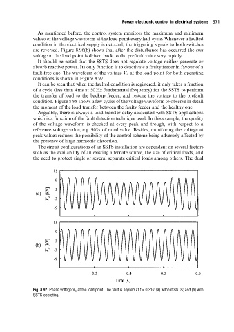
It should be noted that the SSTS does not regulate voltage neither generate or
absorb reactive power. Its only function is to deactivate a faulty feeder in favour of a
fault-free one. The waveform of the voltage V a at the load point for both operating
conditions is shown in Figure 8.97.
It can be seen that when the faulted condition is registered, it only takes a fraction
of a cycle (less than 4 ms at 50 Hz fundamental frequency) for the SSTS to perform
the transfer of load to the backup feeder, and restore the voltage to the prefault
condition. Figure 8.98 shows a few cycles of the voltage waveform to observe in detail
the moment of the load transfer between the faulty feeder and the healthy one.
Arguably, there is always a load transfer delay associated with SSTS applications
which is a function of the fault detection technique used. In this example, the quality
of the voltage waveform is checked at every peak and trough, with respect to a
reference voltage value, e.g. 90% of rated value. Besides, monitoring the voltage at
peak values reduces the possibility of the control scheme being adversely affected by
the presence of large harmonic distortion.
The circuit configurations of an SSTS installation are dependent on several factors
such as the availability of an existing alternate source, the size of critical loads, and
the need to protect single or several separate critical loads among others. The dual
Fig. 8.97 Phase voltage V a at the load point. The fault is applied at t = 0.31s: (a) without SSTS; and (b) with
SSTS operating.