
Page 390 - Power Electronic Control in Electrical Systems
P. 390
//SYS21/F:/PEC/REVISES_10-11-01/075065126-CH008.3D ± 370 ± [290±372/83] 17.11.2001 10:29AM
370 Transient studies of FACTS and Custom Power equipment
Fig. 8.95 SSTS controller implemented in PSCAD/EMTDC.
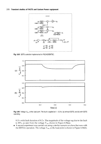
Fig. 8.96 Voltage V rms at the load point. The fault is applied at t = 0.31s: (a) without SSTS; and (b) with SSTS
operating.
0.31 s with fault duration of 0.2 s. The magnitude of the voltage sag due to the fault
is 30%, as seen from the voltage V rms shown in Figure 8.96(a).
. A second experiment was carried out using a similar scenario as above but now with
the SSTS in operation. The voltage V rms at the load point is shown in Figure 8.96(b).