
Page 177 - Power Electronics Handbook
P. 177
A.C. chopper regulation 169
S.
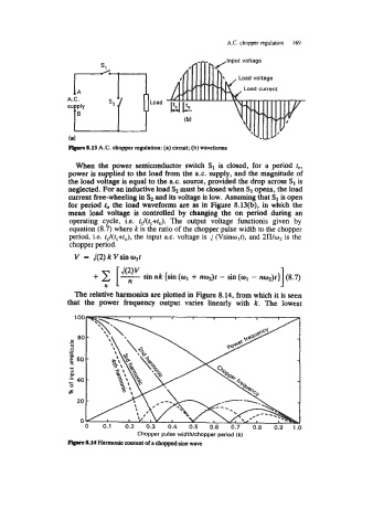
prrvC8.13 A.C. cbopper regulation: (a) circuit; (b) waveforms
When the power semiconductor switch S1 is closed, for a period fc,
power is supplied to the load from the 8.c. supply, and the magnitude of
the load voltage is equal to the a.c. source, provided the drop across SI is
neglected. For an inductive load S, must be closed when S1 opens, the load
current free-wheeling in S, and its voltage is low. Assuming that S1 is open
for period to the load waveforms are as in Figure 8.13(b), in which the
mean load voltage is controlled by changing the on period during an
operating cycle, i.e. t&,+f,). The output voltage functionis given by
equation (8.7) where k is the ratio of the chopper pulse width to the chopper
period, i.e. fJ(f,+t,), the input a.c. voltage is ,/ (Vsinw,f), and 2Ww2 is the
chopper period.
V = J(2) k Vsin wit
1
sin nk {sin (wl + nq)t - sin (a1 - nq)r} (8.7)
n
The relative harmonics are plotted in Figure 8.14, from which it is seen
that the power frequency output varies linearly with k. The lowest
Chopper pulse widthlchopper period (k)
plpl* 8.14 Humonic content of a choppbd sine wave