
Page 180 - Power Electronics Handbook
P. 180
172 Static switches
Filter Load
I
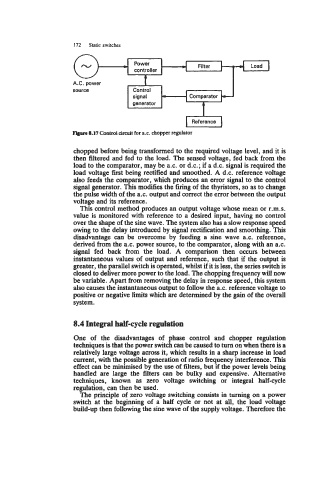
A.C. power
source
signal
Figure 8.17 Control circuit for ax. chopper regulator
chopped before being transformed to the required voltage level, and it is
then filtered and fed to the load. The sensed voltage, fed back from the
load to the comparator, may be a.c. or d.c.; if a d.c. signal is required the
load voltage first being rectified and smoothed. A d.c. reference voltage
also feeds the comparator, which produces an error signal to the control
signal generator. This modifies the firing of the thyristors, so as to change
the pulse width of the a.c. output and correct the error between the output
voltage and its reference.
This control method produces an output voltage whose mean or r.m.s.
value is monitored with reference to a desired input, having no control
over the shape of the sine wave. The system also has a slow response speed
owing to the delay introduced by signal rectification and smoothing. This
disadvantage can be overcome by feeding a sine wave a.c. reference,
derived from the a.c. power source, to the comparator, along with an a.c.
signal fed back from the load. A comparison then occurs between
instantaneous values of output and reference, such that if the output is
greater, the parallel switch is operated, whilst if it is less, the series switch is
closed to deliver more power to the load. The chopping frequency will now
be variable. Apart from removing the delay in response speed, this system
also causes the instantaneous output to follow the a.c. reference voltage to
positive or negative limits which are determined by the gain of the overall
system.
8.4 Integral half-cycle regulation
One of the disadvantages of phase control and chopper regulation
techniques is that the power switch can be caused to turn on when there is a
relatively large voltage across it, which results in a sharp increase in load
current, with the possible generation of radio frequency interference. This
effect can be minimised by the use of filters, but if the power levels being
handled are large the filters can be bulky and expensive. Alternative
techniques, known as zero voltage switching or integral half-cycle
regulation, can then be used.
The principle of zero voltage switching consists in turning on a power
switch at the beginning of a half cycle or not at all, the load voltage
build-up then following the sine wave of the supply voltage. Therefore the