
Page 397 - Power Electronics Handbook
P. 397
386 Power semiconductor circuit applications
Hall generators placed at the commutator switching positions would
therefore react with the rotor field to produce the required position signals.
A further advantage of the Hall detector is that the voltage reverses with
the direction of the magnetic field so that only two sensors at 90"E to each
other need be used for a four-segment commutator.
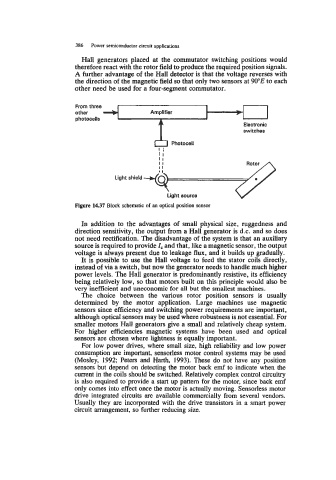
From three
other
photocells
switches
Photocell
Ii
It
I1
Rotor
Light shield
Light source
Figure 14.37 Block schematic of an optical position sensor
In addition to the advantages of small physical size, ruggedness and
direction sensitivity, the output from a Hall generator is d.c. and so does
not need rectification. The disadvantage of the system is that an auxiliary
source is required to provide 1, and that, like a magnetic sensor, the output
voltage is always present due to leakage flux, and it builds up gradually.
It is possible to use the Hall voltage to feed the stator coils directly,
instead of via a switch, but now the generator needs to handle much higher
power levels. The Hall generator is predominantly resistive, its efficiency
being relatively low, so that motors built on this principle would also be
very inefficient and uneconomic for all but the smallest machines.
The choice between the various rotor position sensors is usually
determined by the motor application. Large machines use magnetic
sensors since efficiency and switching power requirements are important,
although optical sensors may be used where robustness is not essential. For
smaller motors Hall generators give a small and relatively cheap system.
For higher efficiencies magnetic systems have been used and optical
sensors are chosen where lightness is equally important.
For low power drives, where small size, high reliability and low power
consumption are important, sensorless motor control systems may be used
(Mosley, 1992; Peters and Harth, 1993). These do not have any position
sensors but depend on detecting the motor back emf to indicate when the
current in the coils should be switched. Relatively complex control circuitry
is also required to provide a start up pattern for the motor, since back emf
only comes into effect once the motor is actually moving. Sensorless motor
drive integrated circuits are available commercially from several vendors.
Usually they are incorporated with the drive transistors in a smart power
circuit arrangement, so further reducing size.