
Page 166 - Power Electronics Handbook
P. 166
A3q
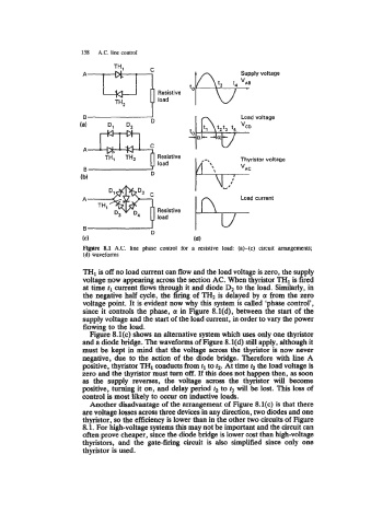
158 A.C. line control
Resistive
0 D load
(a) Dl D2
C
A
TH1 THz Resistive
load
B
(b) D
Figure 8.1 A.C. line phase control for a resistive load (a)-(c) circuit arrangements;
(d) waveforms
is
TH1 off no load current can flow and the load voltage is zero, the supply
voltage now appearing across the section AC. When thyristor TH1 is fired
at time tl current flows through it and diode D2 to the load. Similarly, in
the negative half cycle, the firing of TH2 is delayed by (Y from the zero
voltage point. It is evident now why this system is called 'phase control',
since it controls the phase, 01 in Figure 8.l(d), between the start of the
supply voltage and the start of the load current, in order to vary the power
flowing to the load.
Figure 8.l(c) shows an alternative system which uses only one thyristor
and a diode bridge. The waveforms of Figure 8.l(d) still apply, although it
must be kept in mind that the voltage across the thyristor is now never
negative, due to the action of the diode bridge. Therefore with line A
positive, thyristor TH1 conducts from tl to t2. At time t2 the load voltage is
zero and the thyristor must turn off. If this does not happen then, as soon
as the supply reverses, the voltage across the thyristor will become
positive, turning it on, and delay period t2 to t3 will be lost. This loss of
control is most likely to OCCUT on inductive loads.
Another disadvantage of the arrangement of Figure 8.l(c) is that there
are voltage losses across three devices in any direction, two diodes and one
thyristor, so the efficiency is lower than in the other two circuits of Figure
8.1. For high-voltage systems this may not be important and the circuit can
often prove cheaper, since the diode bridge is lower cost than high-voltage
thyristors, and the gate-firing circuit is also simplified since only one
thyristor is used.