
Page 162 - Power Electronics Handbook
P. 162
154 Static switches
source, but since transformers saturate if operated in a d.c. mode they need
to be driven at high frequency by an oscillator, the a.c. output from the
secondaries being rectified and smoothed before being applied to the gates of
the power semiconductors. Figure 7.4fc) shows a modification for driving
the reversing contactor of Figure 7.l(c), where the forwardheverse control
protection circuitry ensures that only one of the sets of power drive systems
can be activated at any time.
In all the circuits shown in Figure 7.4 the terminal at A deactivates the
drive circuit and so turns the contactor off. This can be as a result of a
signal derived from a protection circuit, such as an overtemperature sensot
located in the load being controlled or an overcurrent detector measuring
the load or power semiconductor current. It is also relatively easy to sense
the zero crossing points of the a.c. supply and to ensure that the on control
is only activated when the supply is passing through its zero point, so that
radio frequency interference generation is minimised. Therefore the
contactors driven by the circuits shown in Figure 7.4 would only be turned
on if control terminals A and C are both active and no fault signals had been
detected on line D.
+vJTQ THI Tr2 THZ TH2
b;' -Devicesfired
ov
--I L i n hna*-J
(b)
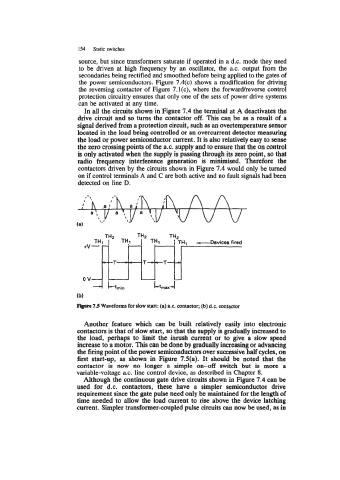
Figwe 7.5 Waveforms for slow start: (a) a.c. Contactor; (b) d.c. contactor
Another feature which can be built relatively easily into electronic
contactors is that of slow start, so that the supply is gradually increased to
the load, perhaps to limit the inrush current or to give a slow speed
increase to a motor. This can be done by gradually increasing or advancing
the firing point of the power semiconductors over successive half cycles, on
first start-up, as shown in Figure 7.5(a). It should be noted that the
contactor is now no longer a simple on-off switch but is more a
variable-voltage a.c. line control device, as described in Chapter 8.
Although the continuous gate drive circuits shown in Figure 7.4 can be
used for d.c. contactors, these have a simpler semiconductor drive
requirement since the gate pulse need only be maintained for the length of
time needed to allow the load current to rise above the device latching
current. Simpler transformer-coupled pulse circuits can now be used, as in