
Page 159 - Power Electronics Handbook
P. 159
152 Static switches
The mean current of diode D3 is also small, the peak current being
VV(C/Ll) at a voltage of V.
Alternative commutation circuits may be used for static switching, and
these are illustrated in Chapter 11.
7.4 Control and protection circuits
If the load for an a.c. contactor were resistive, it would be sufficient to fire
each power semiconductor (thyristor or triac) with a single pulse at the
start of each a.c. cycle, the pulse width being larger than the turn-on time
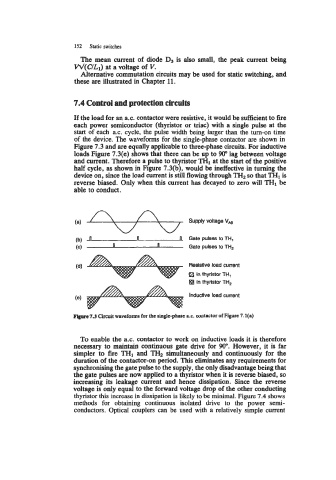
of the device. The waveforms for the single-phase contactor are shown in
Figure 7.3 and are equally applicable to three-phase circuits. For inductive
loads Figure 7.3(e) shows that there can be up to 90" lag between voltage
and current. Therefore a pulse to thyristor TH1 at the start of the positive
half cycle, as shown in Figure 7.3(b), would be ineffective in turning the
device on, since the load current is still flowing through TH2 so that TH1 is
reverse biased. Only when this current has decayed to zero will TH1 be
able to conduct.
n fl Gate pulses to TH,
(b) n
(c) (I Gate pulses to TH,
(d) Reslstlve load current
0 in thyristor TH,
in thyristor TH,
Inductive load current
(e)
F@rc 7.3 Circuit waveforms for the single-phase a.c. contactor of Figure 7.l(a)
To enable the a.c. contactor to work on inductive loads it is therefore
necessary to maintain continuous gate drive for 90". However, it is far
simpler to fire TH1 and THz simultaneously and continuously for the
duration of the contactor-on period. This eliminates any requirements for
synchronising the gate pulse to the supply, the only disadvantage being that
the gate pulses are now applied to a thyristor when it is reverse biased, so
increasing its leakage current and hence dissipation. Since the reverse
voltage is only equal to the forward voltage drop of the other conducting
thyristor this increase in dissipation is likely to be minimal. Figure 7.4 shows
methods for obtaining continuous isolated drive to the power semi-
conductors. Optical couplers can be used with a relatively simple current