
Page 173 - Power Electronics Handbook
P. 173
Phase control 165
0
m
-
m
4-
60-
U
0 -
m
-
20
Firing angle ( a) in degrees
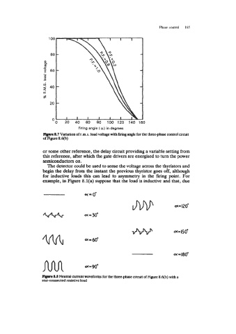
Flgwe 8.7 Variation of r.m.s. load voltage with firing angle for the three-phase control circuit
of Figure 84b)
or some other reference, the delay circuit providing a variable setting from
this reference, after which the gate drivers are energised to turn the power
semiconductors on.
The detector could be used to sense the voltage across the thyristors and
begin the delay from the instant the previous thyristor goes off, although
for inductive loads this can lead to asymmetry in the firing point. For
example, in Figure 8.l(a) suppose that the load is inductive and that, due
Mn a-90'
-8.8 Neutral current waveforms for the three-phase circuit of Figure 8.qb) with B
star-connected resistive load