
Page 220 - Power Electronics Handbook
P. 220
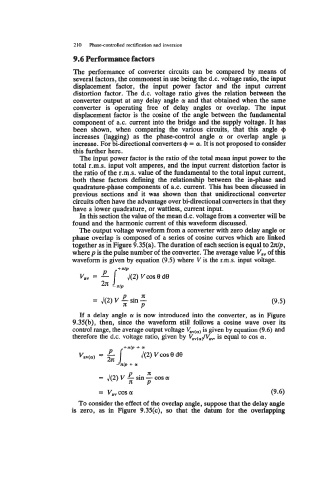
210   Phasecontrolled rectification and inversion
                       9.6 Performance factors

                       The  performance of  converter circuits can  be  compared  by  means  of
                       several factors, the commonest in use being the d.c. voltage ratio, the input
                       displacement  factor,  the  input  power  factor  and  the  input  current
                       distortion factor.  The d.c.  voltage  ratio gives the relation between the
                       converter output at any delay angle 01  and that obtained when the same
                       converter  is  operating  free  of  delay  angles  or  overlap.  The  input
                       displacement factor is the cosine of the angle between the fundamental
                       component of  a.c. current into the bridge and the supply voltage. It has
                       been  shown,  when  comparing  the  various  circuits,  that  this  angle  Cp
                       increases  (lagging)  as  the  phase-control  angle  01  or  overlap  angle  p
                       increase. For bi-directional converters Cp = a. It is not proposed to consider
                       this further here.
                         The input power factor is the ratio of the total mean input power to the
                       total r.m.s.  input volt amperes, and the input current distortion factor is
                       the ratio of  the r.m.s. value of  the fundamental to the total input current,
                       both  these  factors defining the  relationship between  the  in-phase  and
                       quadrature-phase components of  a.c. current. This has been discussed in
                       previous sections and  it  was  shown  then  that  unidirectional  converter
                       circuits often have the advantage over bi-directional converters in that they
                       have a lower quadrature, or wattless, current input.
                         In this section the value of the mean d.c. voltage from a converter will be
                       found and the harmonic current of  this waveform discussed.
                         The output voltage waveform from a converter with zero delay angle or
                       phase overlap is composed of  a series of  cosine curves which are linked
                       together as in Figure 9.35(a). The duration of each section is equal to h/p,
                       where p is the pulse number of  the converter. The average value V,,  of this
                       waveform is given by  equation (9.5) where V is the r.m.s.  input voltage.
                                *
                         Vav  = -    + dP
                                        J(2) Vcos 8 de
                                2~  -r/p
                                            n
                             = 42) V  P  sin -                                     (9.5)
                                            P
                         If  a delay angle a is now  introduced into the converter, as in  Figure
                       9.35(b),  then,  since  the  waveform still  follows a  cosine wave  over  its
                       control range, the average output voltage Vav(a) is given by equation (9.6) and
                       therefore the d.c. voltage ratio, given by  VavcajVa,,, is equal to cos a.
                                      +nlp + a
                         Vav(a)  =  P       ~(2)vcosede
                                    -nlp  + a


                               = Vavcos(Y                                          (9.6)
                         To consider the effect of  the overlap angle, suppose that the delay angle
                       is  zero,  as in  Figure  9.35(c),  so that  the  datum  for  the  overlapping