
Page 62 - Power Electronics Handbook
P. 62
Series and parallel operation 55
As seen from the characteristics of Figure 1.3 l(b), the reference voltage
is not strictly constant, but varies with the current through the device.
There is therefore an impedance 2, associated with this, called the
dynamic impedance and given by equation ( 1.21) where AVz and AIz are the
voltage and current at any point on the characteristic. Dynamic impedance
curves are illustrated in Figure 1.31(d).
(1.21)
1.14 Series and parallel operation
Semiconductors are available today with the ability of controlling many
megawatts of power, therefore it is only in very specialised applications
that several devices need to be connected in series or in parallel, in order to
increase the voltage or current rating, respectively, over that available
from a single device. The techniques for doing so are illustrated in this
section with respect to the thyristor, although these apply equally to any of
the other power semiconductors described in the book.
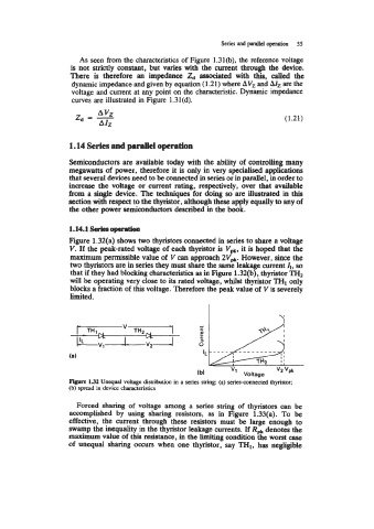
Figure 1.32(a) shows two thyristors connected in series to share a voltage
V. If the peak-rated voltage of each thyristor is V,, it is hoped that the
maximum permissible value of V can approach 2V*. However, since the
two thyristors are in series they must share the same leakage current I,, so
that if they had blocking characteristics as in Figure 1.32(b), thyristor TH2
will be operating very close to its rated voltage, whilst thyristor THI only
blocks a fraction of this voltage. Therefore the peak value of V is severely
limited.
V
(8)
v2 vpk
(b) v1 Voltage
Figure 1.32 Unequal voltage distribution in a series string: (a) series-connected thyristor;
@) spread in device characteristics
Forced sharing of voltage among a series string of thyristors can be
accomplished by using sharing resistors, as in Figure 1.33(a). To be
effective, the current through these resistors must be large enough to
swamp the inequality in the thyristor leakage currents. If RPk denotes the
maximum value of this resistance, in the limiting condition the worst case
of unequal sharing occurs when one thyristor, say TH1, has negligible