
Page 19 - Power Quality in Electrical Systems
P. 19
Introduction 3
Ideal 60 Hz sinewave
200
150
100
Voltage [V] 50
0
−50
−100
−150
−200
0 0.005 0.01 0.015 0.02 0.025 0.03
Time [sec]
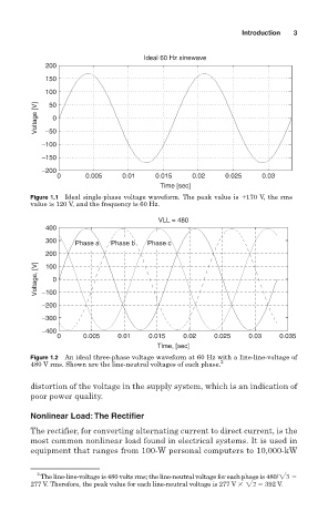
Figure 1.1 Ideal single-phase voltage waveform. The peak value is 170 V, the rms
value is 120 V, and the frequency is 60 Hz.
VLL = 480
400
300
Phase a Phase b Phase c
200
Voltage, [V] −100
100
0
−200
−300
−400
0 0.005 0.01 0.015 0.02 0.025 0.03 0.035
Time, [sec]
Figure 1.2 An ideal three-phase voltage waveform at 60 Hz with a line-line-voltage of
2
480 V rms. Shown are the line-neutral voltages of each phase.
distortion of the voltage in the supply system, which is an indication of
poor power quality.
Nonlinear Load:The Rectifier
The rectifier, for converting alternating current to direct current, is the
most common nonlinear load found in electrical systems. It is used in
equipment that ranges from 100-W personal computers to 10,000-kW
2
The line-line-voltage is 480 volts rms; the line-neutral voltage for each phase is 480/23
277 V. Therefore, the peak value for each line-neutral voltage is 277 V 22 392 V.