
Page 20 - Power Quality in Electrical Systems
P. 20
4 Chapter One
D1 D3 D5
a
Three-Phase b
service
c I load
L
D2 D4 D6
(a)
Phase
current
I L
Electrical
degrees
60 120 180 240 300 360
−I L
(b)
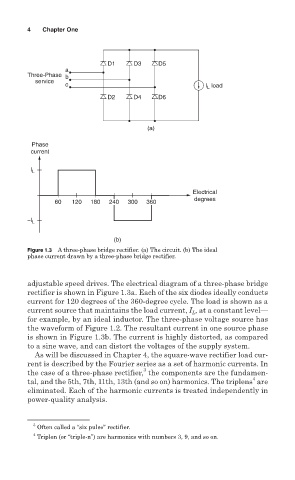
Figure 1.3 A three-phase bridge rectifier. (a) The circuit. (b) The ideal
phase current drawn by a three-phase bridge rectifier.
adjustable speed drives. The electrical diagram of a three-phase bridge
rectifier is shown in Figure 1.3a. Each of the six diodes ideally conducts
current for 120 degrees of the 360-degree cycle. The load is shown as a
current source that maintains the load current, I , at a constant level—
L
for example, by an ideal inductor. The three-phase voltage source has
the waveform of Figure 1.2. The resultant current in one source phase
is shown in Figure 1.3b. The current is highly distorted, as compared
to a sine wave, and can distort the voltages of the supply system.
As will be discussed in Chapter 4, the square-wave rectifier load cur-
rent is described by the Fourier series as a set of harmonic currents. In
3
the case of a three-phase rectifier, the components are the fundamen-
4
tal, and the 5th, 7th, 11th, 13th (and so on) harmonics. The triplens are
eliminated. Each of the harmonic currents is treated independently in
power-quality analysis.
3
Often called a “six pulse” rectifier.
4
Triplen (or “triple-n”) are harmonics with numbers 3, 9, and so on.