
Page 195 - Practical Design Ships and Floating Structures
P. 195
170
equations of motions have six degrees of freedom and a polynomial of the 12~ degree is obtained to
determine the eigenvalues, a very difficult task to be treated analytically. For a single ship in SPM or a
FPSO provided with a turret, there are only three equations of motion and the longitudinal movement
equation is independent of the others and is stable. This reduces the problem to the solution of a 4"
degree polynomial. Even in this case a complex algebraic manipulation is necessary to obtain an
analytical solution. However, the use of symbolic computation systems, avoiding the long algebraic
manipulation, makes possible the analytical treatment of this problem. Although, the eigenvalues can
be expressed as functions of the system parameters, the derived expressions arc cven too extensive (see
Matter et a1 (2001 b)).
In the next sections three cases studies concerning the use of the derived expressions in the selection of
stabilizer device for a TMS, in the definition of the main dimensions of the floating unit in the
preliminary design stage and in the analysis of the offloading operation of a DICAS mooring system.
4 STABILIZER DEVICE SELECTION
A very important factor in the design of a FPSO is the longitudinal position of the Turret. If it is
located close to the ship's bow end, forward of the critical point, the equilibria can be stable in the
horizontal plane, but the ship can be submitted to large vertical movements, which could affect
seriously the structure. On the other hand a central turret makes the system unstable.
Here, the selection of a stabilizer device to be used in a FPSO, to operate in 1000 meters water depth is
presented with the turret positioned at 0.2 L forward of the midship section (astern of the critical point).
The Esso Osaka hull was used as the FPSO with the maneuvering derivatives obtained from Abkowitz
(1980). The position of the critical point ucri, is expressed by (Sphaier, Femandes and Correa, 2000a,
2000b):
TABLE I
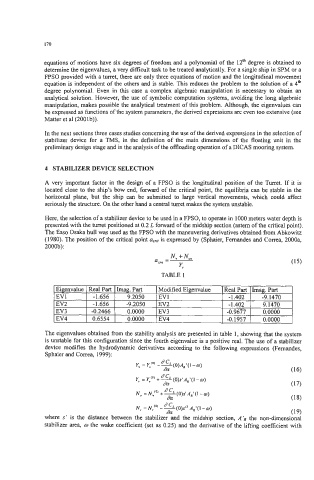
The eigenvalues obtained from the stability analysis are presented in table 1, showing that the system
is unstable for this configuration since the fourth eigenvalue is a positive real. The use of a stabilizer
device modifies the hydrodynamic derivatives according to the following expressions (Femandes,
Sphaier and Correa, 1999):
Y" = Y"CO) - =(O)A,'(I - 0)
da (16)
Y, = Y,'"++d(O)s'A,'(1-o)
da (17)
N, = N,"' +~(O)s'A,'(I-m)
da (18)
N, = N,"' - s(0)ss2 ,4,'(1 - 0)
da (19)
where s ' is the distance between the stabilizer and the midship section. A 'R the non-dimensional
. ..
stabilizer area, o the wake coefficient (set as 0.25) and the deriiative of the lifting coefficient with