
Page 196 - Practical Design Ships and Floating Structures
P. 196
171
respect to the attack angle can be obtained from Thwaites (1987). The substitution of the Eqns. 16 and
18 in Eqn. 15 gives the area of the stabilizer necessary to change the position of the critical point:
To stabilize the system the new device must have a non-dimensional (A,/L2) area equal to 0.002935
with the aspect ratio equal to 2.4. This means that two rudders (see figure 2) should be used to stabilize
the system, each one 27.0 meters high and 11.2 meters large. The eigenvalues for the modified system
are also presented in table 1. All of them have negative real part confirming that the system is stable.
Figure 2: Two rudders Configuration
5 PRELIMINARY DESIGN
In the preliminary design stages, a sensibility analysis of the influence the main parameters of the ship
(L, B, T and Cb) have on her stability can be performed. Such analysis goes through the estimation of
the hydrodynamics derivatives of the ship from her main characteristics (Clarke et a1 (1982)).
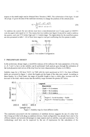
Stability maps for a 300 kton VLCC, in TMS with the turret positioned at 0.25 L for three different
-v\, ‘7:
drafts are presented in figure 3, where the length and the beam of the ship were varied. According to
these figures, for a fixed beam, the range of possible length to have a stable ship, increase with the
decrease of the draft, which means that the stability range increases for greater BRratios.
80.0 - -~ ._._.
Legend:
h 1 Boundaries ~ ~ I
E 70.0 , .\ ~, I Draft = 17.0 meters I
-
v \ ~ . . . . . . -.
I ~, \I Draft = 16.0 meters
5 t - - - Draft = 15.0 meters
-0 11,1 I,,
([I 60.0 \ ‘\I 1
2
m p--i
Region I - Inside boundary = Stable
50.0 Region I1 - Outside boundary = Unstable, ,
-..-,~---~ ______
~~~~~
201
This conclusion associated with the installation of stabilizer devices suggests the use of a ship form
like a barge provided with skegs as stabilizer devices. Such configuration has already been used in the
offshore industry and presents advantages in many aspects such as stability, cost and construction. The
methodology used here can be improved by the use of expressions for the calculation of the