
Page 215 - Practical Design Ships and Floating Structures
P. 215
190
3 VLFS MODELS AND EXPERIMENTS
In order to validate numerical results and to clarify the trend of wave drift forces of VLFS, model
experiments were carried out in the towing tank (100m length, 8m width, 3.5m depth) of Yokohama
National University. Semi-submersible units and pontoon units supported elastic floating models were
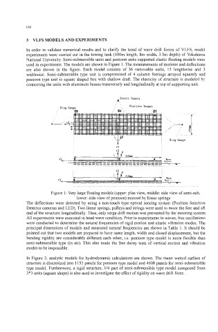
used in experiments. The models are shown in Figure 1. The measurements of motions and deflections
are also shown in the figure. Each model consists of 36 removable units, 12 lengthwise and 3
widthwise. Semi-submersible type unit is compromised of 4 column footings arrayed squarely and
pontoon type unit is square shaped box with shallow draft. The elasticity of structure is modeled by
connecting the units with aluminum beams transversely and longitudinally at top of supporting unit.
Sensor Camera
J.,
..
.
. ..
.
. Ring Gauge . , , . Position Target
'.,;'
i!a : a If
....................................................................................................
Figure 1 : Very large floating models (upper: plan view, middle: side view of semi-sub,
lower: side view of pontoon) moored by linear springs
The deflections were detected by using a non-touch type optical sensing system (Position Sensitive
Detector cameras and LED). Two linear springs, pulleys and strings were used to moor the fore and aft
end of the structure longitudinally. Thus, only surge drift motion was prevented by the mooring system.
All experiments were executed in head wave condition. Prior to experiments in waves, free oscillations
were conducted to determine the natural frequencies of rigid motion and elastic vibration modes. The
principal dimensions of models and measured natural frequencies are shown in Table 1. It should be
pointed out that two models are prepared to have same length, width and closed displacement, but the
bending rigidity are considerably different each other, Le. pontoon type model is more flexible than
semi-submersible type (in air). This also made the free decay tests of vertical motion and vibration
modes to be impossible.
In Figure 2, analytic models for hydrodynamic calculations are shown. The mean wetted surface of
structure is discretized into 1152 panels for pontoon type model and 4608 panels for semi-submersible
type model. Furthermore, a rigid structure, 114 part of semi-submersible type model composed from
3*3 units (square shape) is also used to investigate the effect of rigidity on wave drift force.