
Page 513 - Practical Design Ships and Floating Structures
P. 513
488
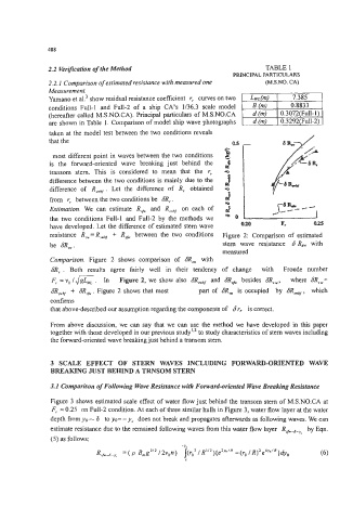
2.2 Verification of the Method TABLE 1
PRINCIPAL PARTICULARS
2.2.1 Comparison of estimated resistance with measured one (M.S.NO. CA)
Measurement.
Yamano et al? show residual resistance coefficient r, curves on two 7.385
conditions Full-1 and Full-2 of a ship CA's 1136.3 scale model 0.8833
(hereafter called M.S.NO.CA). Principal particulars of M.S.NO.CA
are shown in Table 1. Comparison of model ship wave photographs
taken at the model test between the two conditions reveals
that the
most different point in waves between the two conditions
is the forward-oriented wave breaking just behind the
transom stem. This is considered to mean that the r,
difference between the two conditions is mainly due to the
difference of R,,, . Let the difference of R, obtained
from r, between the two conditions be 6R,.
Estimation. We can estimate R, and R,wbJ on each of
the two conditions Full-1 and Full-2 by the methods we
have developed. Let the difference of estimated stern wave 0.20 F. 0.25
resistance R,=R,,wb, + R, between the two conditions Figure 2: Comparison of estimated
be 6R,. stern wave resistance 6R, with
measured
Comparison. Figure 2 shows comparison of SR, with
SR, . Both results agree fairly well in their tendency of change with Froude number
F, = vo IK. In Figure 2, we show also SR, and 6R, besides SRSw, where 6RSw=
SR,, + CTR,~~. Figure 2 shows that most part of SR, is occupied by SR,, which
confirms
that above-described our assumption regarding the components of 6r, is correct.
From above discussion, we can say that we can use the method we have developed in this paper
together with those developed in our previous study'.2 to study characteristics of stem waves including
the forward-oriented wave breaking just behind a transom stem.
3 SCALE EFFECT OF STERN WAVES INCLUDING FORWARD-ORIENTED WAVE
BREAKING JUST BEHIND A TRNSOM STERN
3. I Comparison of Following Wave Resistance with Forward-oriented Wave Breaking Resistance
Figure 3 shows estimated scale effect of water flow just behind the transom stern of M.S.NO.CA at
F, = 0.25 on Full-2 condition. At each of three similar hulls in Figure 3, water flow layer at the water
depth from yo=- 6 to yo= - y, does not break and propagates afterwards as following waves. We can
estimate resistance due to the remained following waves from this water flow layer R,-6-yt by Eqn.
(5) as follows:
-YC
R,,fi-8-y, = ( p B,g3" /2v,n) l(roz / R"2){e2yn'R -(ro / R)2e4y0'R}dyo (6)