
Page 536 - Practical Design Ships and Floating Structures
P. 536
51 1
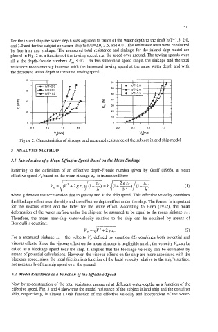
For the inland ship the water depth was adjusted to ratios of the water depth to the draft h/T=1.5, 2.0,
and 3.0 and for the subject container ship to h/T=2.0,2.6, and 4.0 . The resistance tests were conducted
by free trim and sinkage. The measured total resistance and sinkage for the inland ship model are
plotted in Fig. 2 as a function of the towing speed, e.g. the speed over ground. The towing speeds were
all at the depth-Froude numbers FA I 0.7. In this subcritical speed range, the sinkage and the total
resistance monotonously increase with the increased towing speed at the same water depth and with
the decreased water depth at the same towing speed.
40 I
I 1 I I 70
60
- 50
E 40
E
I 30
N=
20
10
0
00 0.5 1 .a 1.5 0.0 0.5 1 .a 1.5
V,Im/sI V,Im/sl
Figure 2: Characteristics of sinkage and measured resistance of the subject inland ship model
3 ANALYSIS METHOD
3.1 Introduction of a Mean Effective Speed Based on the Mean Sinkage
Referring to the definition of an effective depth-Froude number given by Graff (1963), a mean
effective speed VE based on the mean sinkage z,, is introduced here
where g denotes the acceleration due to gravity and V the ship speed. This effective velocity combines
the blockage effect near the ship and the effective depth-effect under the ship. The former is important
for the viscous effect and the latter for the wave effect. According to Horn (1932), the mean
deformation of the water surface under the ship can be assumed to be equal to the mean sinkage z,, .
Therefore, the mean near-ship water-velocity relative to the ship can be obtained by means of
Bernoulli’s equation:
v, =Jv2+2gzv (2)
For a measured sinkage zv, the velocity VB defined by equation (2) combines both potential and
viscous effects. Since the viscous effect on the mean sinkage is negligible small, the velocity V, can be
called as a blockage speed near the ship. It implies that the blockage velocity can be estimated by
means of potential calculations. However, the viscous effects on the ship are more associated with the
blockage speed, since the local friction is a function of the local velocity relative to the ship’s surface,
not necessarily of the ship speed over the ground.
3.2 Model Resbtance as a Function of the Effective Speed
Now by re-construction of the total resistance measured at different water-depths as a function of the
effective speed, Fig. 3 and 4 show that the model resistance of the subject inland ship and the container
ship, respectively, is almost a unit function of the effective velocity and independent of the water-