
Page 535 - Practical Design Ships and Floating Structures
P. 535
510
different blockage correction caused by ships moving in a towing tank and in an operathg area
considered. A large number of theoretical and experimental investigations has been devoted to this
problem. As documented by Gross and Watanabe (1972), there are two methods for Comting these
boundary effects. One is to correct the resistance and the other to correct the speed. These two methods
are combined in the so-called Schlichting’s hypothesis (1934). According to his hypothesis the wave
resistance is the same at the same wave length corresponding to different speeds in deep and shallow
water and the viscous resistance is the same at the same speed relative to the water at different water-
depths. The speed change due to the blockage effect can be empirically estimated either by using the
simple control parameter defined by Schlichting (1 934) Without correcting the wall effects or by using
a control parameter based on the hydraulic radius given by Landweber (1 939), which is also applicable
for a real shape of the channel section. The speed change at each parameter value can be either read in
the Corresponding diagrams or calculated from the empirical formulae, e.g. Lackenby (1963). For
nmow channels, like many small towing tanks, the mean flow theory based on the one-dimensional
continuity and Bernoulli’s equation has been widely used. These tow equations lead to a mean flow
over the whole channel section. The mean flow change near the ship’s surface can then be obtained by
means of an empirical factor, e.g. Emerson (1 959) using a constant value independent of the speed and
Kim (1 963) using a factor depending on speed and block coefficient.
The present study focuses on a physically reasonable and practically applicable method for resistance
and propulsion prediction of ships in shallow water at a subcritical speed. After analyzing the
resistance characteristics at different water-depths, a new method is proposed for predicting the total
resistance which can be considered as a unit function of the effective speed defined by the mean
sinkage. Accordingly, the propulsion tests will be conducted at a ship self-propulsion point
corresponding to the effective speed. It can be shown that the delivered power at propeller seams to be
a unit function of the blockage speed. In comparison to the earlier empirical approximation, the new
method includes one additional information, namely the mean sinkage, which is an individual quantity
depending both on the ship geometry and speed as well as on the geometry configuration of the
operating area. Since the mean sinkage can be accurately calculated by means of the potential theory,
for instance using an extended shallow-water approximation, this new method could impact the
resistance and propulsion prediction of the ship performance in shallow water.
2 RESISTANCE PERFORMANCE
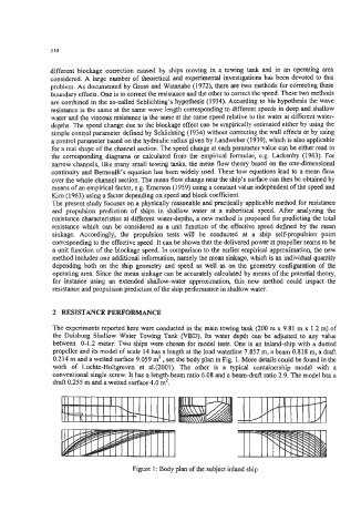
The experiments reported here were conducted in the main towing tank (200 m x 9.81 m x 1.2 m) of
the Duisburg Shallow Water Towing Tank (VBD). Its water depth can be adjusted to any value
between 0-1.2 meter. Two ships were chosen for model tests. One is an inland-ship with a ducted
propeller and its model of scale 14 has a length at the load waterline 7.857 m, a beam 0.818 m, a draft
0.214 m and a wetted surface 9.059 mz , see the body plan in Fig. 1. More details could be found in the
work of Lochte-Holtgreven et al.(2001). The other is a typical containership model with a
conventional single screw. It has a length-beam ratio 6.08 and a beam-draft ratio 2.9. The model has a
draft 0.255 m and a wetted surface 4.0 mz.
Figure 1 : Body plan of the subject inland ship