
Page 203 - Practical Power System and Protective Relays Commissioning
P. 203
Protection Relays Chapter | 18 203
The following are typical operating characteristics in use:
SI t 5 0:14
I 0:0221
VI t 5 13:5
I 2 1
EI t 5 80
I 221
Long time standby earth fault t 5 120 where t 5 relay operating time(s),
I 2 1
I 5 current (multiple of plug setting).
18.5.3 PRINCIPLES OF TIME/CURRENT GRADING
18.5.3.1 Discrimination by Time
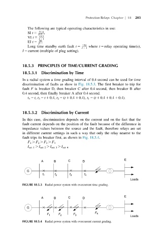
In a radial system a time grading interval of 0.4 second can be used for time
discrimination of faults as show in Fig. 18.5.3. The first breaker to trip for
fault F is breaker D, then breaker C after 0.4 second, then breaker B after
0.4 second, then finally breaker A after 0.4 second.
t 4 5 t, t 3 5 t 1 0.4, t 2 5 (t 1 0.4 1 0.4), t 1 5 (t 1 0.4 1 0.4 1 0.4).
18.5.3.2 Discrimination by Current
In this case, discrimination depends on the current and on the fact that the
fault current depends on the position of the fault because of the difference in
impedance values between the source and the fault, therefore relays are set
in different current settings in such a way that only the relay nearest to the
fault trips its breaker first, as shown in Fig. 18.5.4.
F 1 . F 2 . F 3 . F 4
I set 1 . I set 2 . I set 3 . I set 4
FIGURE 18.5.3 Radial power system with overcurrent time grading.
FIGURE 18.5.4 Radial power system with overcurrent current grading.