Page 155 - Practical Ship Design
P. 155

122                                                             Chapter 4

             ~-
              V  1           W                               Z               1  AA
              ~
                  Resistance                       Powering
             7                                     Ct inclusive
             8    service speed Vk                 Pe = 0.0697 . Ct . S . V3(kW)
             9    Froude Fn = 0.1 64 Vk/&          prop diameter
             10   Rn = 2.636 x 1 O6  Fn . L’       service RPM
             11                                    QPC = 0.84 - (Nd)/lOOOO
             12                                    Ps = Pe/QPC (kW)
             13                                    trial margin
             14   Cb                               Ps (trial) (kW)
             15   A                                service margin
             16   C                                Ps (service) (kW)
             17   S = C/AL                         derating
             18   ’s’ = 1.01 66 S/A‘”              MCR (kW)
              19   Lb (basis or model)
             20   Bb                               C app as Yo Ct
             21   Tb                               rudder 1.5%
             22   Rnb                              twin rudders 2.8%
             23   (1 + K)                          shaft bkts and shafts 6%
             24   Ctb                              stabiliser fins 2.8%
             25   Cfd = 0.075/,/-                  bilge keels 1.4%
             26   Cfd (use Rnb)                    powering assumes SW (r = 1.025)
             27   Ctd = Ctb + (1 + K) (Cfd - Cfb)   fb - fall back value
             28   6’ = B(LWL)                      machinery type chosen
             29   T’ = T(Lb/L)
             30   Mumford corrections B & T
             31   Ct corrected L,B,T               approx capacity check
              32   AC (fb = 0.10 x  1@)
             33  c aPP                             depth D
              34   C air                           sheer         camber
              35   Ct inclusive                    D’ corr S & C
              36                                   gross vol L . B . D’ . Cbd
              37                                   deductions
              38                                   additions above upper deck
              39                                   gross cargo cubic
              40                                   structure deduction
              41
              42                                   cargo cubic
                                                                             ~
             ~~

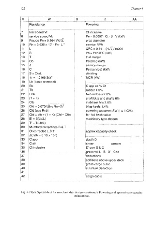
              Fig. 4.19(d). Spreadsheet for merchant ship design (continued). Powering and approximate capacity
                                            calculations.
   150   151   152   153   154   155   156   157   158   159   160