
Page 199 - Practical Ship Design
P. 199
165
1 .oo
0.95
0.90
Cm
0.85
0.80
0.75
0.70
1 .o 2.0 3.0 4.0 5.0
BIT
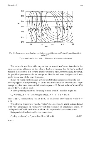
Fig. 6. I. Contours of wetted surface coefficient vs midship area coefficient (C,) and beaddraft
ratio (BIT).
(Taylor metricated) S = C&. S in metres, L in metres, A in tonnes.
The author is unable to offer any advice as to which of these formulae is the
most accurate, although he has always had a preference for Taylor’s method
because this seems to him to have a better scientific basis. Unfortunately, however,
its graphical presentation is not computer friendly and most designers will now
prefer to use one of the other formulae.
It may be worth mentioning as a minor aside that designers used to make use -
for very approximate powering - of the fact that almost all conventional ships
except very fast ones have, at their service speed, a 4? Froude value of about 0.70
or a IC‘ ITTC of about 0.60.
A corresponding statement for today’s more usual C, notation might be:
C,, = about 2.5 x (reducing to about 2.4 x IO-’ if L > 200 m)
The (C I‘ITC value and the first of the C, values quoted above equate when S =
6.03.
The effective horsepower may be “naked”, i.e., as given by a tank test conducted
with “no” appendages or “inclusive” with the resistance of appendages added, or
“ship predicted” with the further addition of a shipmodel correlation factor.
Ship predicted inclusive effective horsepower
P,(ship predicted) = P,(naked) x (1 + x)( 1 +A) (6.20)
where