
Page 129 - Practical Well Planning and Drilling Manual
P. 129
Section 1 revised 11/00/bc 1/17/01 2:56 PM Page 105
1.4.24
Casing Design [ ]
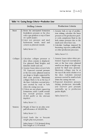
Table 1-6 Casing Design Criteria—Production Liner
Drilling Criteria Production Criteria
Burst 1. Resist the anticipated formation 1. Assume leak at top of produc-
breakdown pressure at the shoe tion tubing; calculate the burst
with a gas gradient to top of liner pressure at the production pack-
(0.1 psi/ft inside). er with completion fluid in the
2. Liner test pressure and mud hole minus pressure due to the
hydrostatic inside, mud and mud used when liner run.
cement as planned outside. 2. Calculate loadings imposed by
fracturing, injection, artificial lift,
Safety factor 1.1. or other production processes.
Safety factor 1.1.
Collapse 1. Calculate collapse pressure at 1. Assume losses taken when per-
shoe when cement is displaced. forated. Expected external pres-
Use planned fluid heights and sure at the loss zone; planned
densities inside and out. mud in use drops to height sup-
2. Assume losses taken at next hole ported by thief zone pressure.
TD. Expected external pressure Maximum collapse may be at
at the loss zone; planned mud in the top of the mud column or at
use drops to height supported by the shoe. Calculate external
thief zone pressure. Maximum pressure exerted by mud in hole
collapse likely to be at the top of when the casing was run.
the liner. Calculate external pres- 2. Expected drawdown pressure
sure exerted by mud in hole during production internally
when the casing was run. and reservoir pore pressure
3. If there are any plastic squeezing externally, up to production
formations, resist 1 psi/ft outside packer depth.
less normal pressure inside
(0.465 psi/ft) at the relevant Safety factor 1.1.
depth(s).
Safety factor 1.1.
Tension 1. Weight of liner in air plus over-
pull allowance of 100,000 lbs.
Safety factor 1.1.
2. Axial loads due to buoyant
weight plus test pressure.
Safety factor 1.75 if deviated along
liner length or 1.5 if vertical.
105