
Page 92 - Practical Well Planning and Drilling Manual
P. 92
Section 1 revised 11/00/bc 1/17/01 2:56 PM Page 68
[ ] Well Design
1.4.10
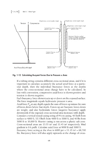
Weights down, nominal weights x lengths Weight down, nominal weight x length
Tension 0 Compression
Weight down, nominal weight x length
Hydraulic force down, Hydraulic force down,
pressure x area pressure x area
Section of thicker walled
casing could be considered
as two separate elements.
Hydraulic force up, Hydraulic force up,
pressure x area pressure x area
Hydraulic force up, Hydraulic force up,
Axial Force (Fa) with depth pressure x area pressure x area
Fig. 1-12 Calculating Buoyant Forces Due to Pressure x Area
If a tubing string contains different cross-sectional areas, and if it is
important to calculate accurately the actual axial force at a partic-
ular depth, then the individual buoyancy forces at the depths
where the cross-sectional areas change have to be calculated. In
line with convention, compressive axial force is shown positive and
tension is shown negative.
Each buoyancy force element acts up or down on the exposed surface.
The force magnitude equals hydrostatic pressure x area.
Axial force F at any depth equals the sum of forces up minus the sum
a
of forces down below that depth. Forces up are buoyant, forces down
are weight, and also hydrostatic forces (negative buoyancy) apply
downwards if the exposed cross-sectional area increases with depth.
5
Consider a vertical mixed casing string of 9 /8 in casing, 40 lbs/ft from
surface to 4000 ft, 53.5 lbs/ft from 4000 ft to 5000 ft, and 40 lbs from
5000 ft to 10,000 ft. Heavier casing is run across a plastic salt zone.
Cross-sectional areas are 15.55 in and 11.45 in respectively. Mud
2
2
gradient is 0.6 psi/ft. Calculate axial force at 9000 ft and 3000 ft.
Buoyancy force acting at the shoe is 6000 psi x 11.45 in = 68,700
2
lbs. Buoyancy force will also apply upwards at the change of cross-
68