
Page 181 - Pressure Vessel Design Manual
P. 181
Design of Vessel Supports 159
where they occur. Overall weights of sections are used in
drte~miriing forces, not uniform weights. Moments due to
eccentric loads are added to the overall moment of the
column.
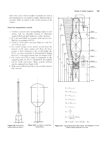
Notes €or nonuniform vessels
1. Combine moments with corresponding weights at each Plane 7
section and use allowable stresses to determine
required shell and skirt thicknesses at the elevation.
2. o A a! and LVP/s/rI arc separate totals and are com- Plane 6
bined in computation of P. O.V.
3. (D/10)"3 is iised in this expression if kips are used. Use
D)"' if Ih are used.
4. For vessels having a lower section several times the
diameter of the upper portion arid where the lower
Plane 5
portion is sliort compared to the overall height, the
P. 0.L'. can more acciirately be determined hy finding
the P.O.V. ofthe upper section alone (see Figure 3-39).
Plane 4
5. For \.essels wliere Wt is large in comparison to the
slipporting skirt, the P. O.V. calculated by this method
may be overly conservative. More accurate methods Plane 3
inay he employed (see Figure 3-40).
6. Make sure to add moment the to any eccentric loads to J Plane 2
total moment.
Plane 1
Figure 3-39. Nonuniform Figure 3-40. Nonuniform vessel illus- Figure 3-41. Typical dimensional data, forces, and loadings on a non-
vessel illustrating Note 4. trating Note 5. uniform vessel supported on a skirt.