
Page 180 - Pressure Vessel Design Manual
P. 180
158 Pressure Vessel Design Manual
Note: P.O.V. may be determined from chart in Figure 3-9. H
and D are in feet; t is in inches.
V = Ct,W, (from Procedure 3-3)
Ft = 0.07TV or 0.25V
whichever is less
Note: If H/D p 3 or T p 0.7 sec, then Ft = 0
Mi, = FtH + %(FH)
Moment at any height hi
Case 2: Nonuniform Vessels
Procedure €or finding period of vibration, moments,
and forces at various planes for nonuniform vessels.
A “nonuniform” vertical vessel is one that vanes in diameter,
thickness, or weight at different elevations. This procedure
distributes the seismic forces and thus base shear, along the
column in proportion to the weights of each section. The
results are a more accurate and realistic distribution of
forces and accordingly a more accurate period of vibration.
The procedure consists of two main steps:
V
Step 1: Determination of period of vibration (P.O.V.), T.
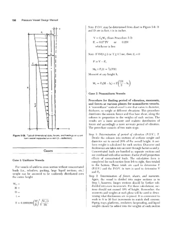
Figure 3-38. Typical dimensional data, forces, and loadings on a uni-
form vessel supported on a skirt (8 =deflection). Divide the column into sections of uniform weight and
diameter not to exceed 20% of the overall height. A uni-
form weight is calculated for each section. Diameter and
thicknesses are taken into account through factors a! and y.
Cases Concentrated loads are handled as separate sections and
not combined with other sections. Factor B will proportion
effects of concentrated loads. The calculation form is
Case 1: Uniform Vessels
completed for each section from left to right, then totaled
to the bottom. These totals are used to determine T
For vessels of uniform cross section without concentrated (P.O.V.) and the P.O.V. in turn is used to determine V
loads (i.e., reboilers, packing, large liquid sections, etc.) and F,.
weight can be assumed to be uniformly distributed over
the entire height. Step 2: Determination of forces, shears, and moments.
Again, the vessel is divided into major sections as in
W, = Step 1; however, longer sections should be further sub-
divided into even increments. For these calculations, sec-
H= tions should not exceed 10% of height. Remember, the
D= moments and weights at each plane will be used in deter-
mining what thicknesses are required. It is convenient to
t=
T = 0.0000265 (E) ‘Pg work in 8 to 10 foot increments to match shell courses.
--
Piping, trays, platforms, insulation, fireproofing, and liquid
weights should be added into the weights of each section