Page 175 - Pressure Vessel Design Manual
P. 175

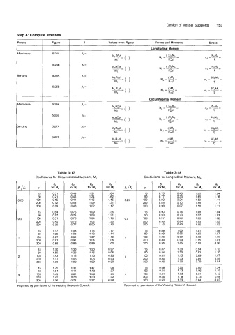
Design of Vessel Supports   153


          Forces           Figure          8            Values from Figure     Forces and Moments         stress

          Membrane         5-24A


                           5-248

          Bending          5-25A


                           5-258


          Membrane         5-26A          Be =


                           5-268          Pf  =

          Bending          5-27A          Pg =

                           5-278          Ph =


                              Table 3-17                                           Table 3-1 8
                   Coefficients for Circumferential Moment, M,            Coefficients for Longitudinal Moment, ML
                            CC       CC       Kc        KC                                          KL       KL
          81 /B*    Y      for N+   for N.   for  M,   for M,   81 /B2    Y     for N,    for N,   for  M,   for M,
                    15      0.31     0.49     1.31      1.84              15     0.75     0.43      1.80     1.24
                    50      0.21     0.46     1.24      1.62              50     0.77     0.33      1.65     1.16
          0.25     100      0.15     0.44     1.16      1.45    0.25     100     0.80     0.24      1.59     1.11
                   200      0.12     0.45     1.09      1.31             200     0.85     0.10      1.58     1.11
                   300      0.09     0.46     1.02      1.17             300     0.90     0.07      1.56     1.11
                    15      0.64     0.75     1.09      1.36              15     0.90     0.76      1.08     1.04
                    50      0.57     0.75     1.08      1.31              50     0.93     0.73      1.07     1.03
          0.5      100      0.51     0.76     1.04      1.16    0.5      100     0.97     0.68      1.06     1.02
                   200      0.45     0.76     1.02      1.20             200     0.99     0.64      1.05     1.02
                   300      0.39     0.77     0.99      1.13             300     1.10     0.60      1.05     1.02
                    15      1.17     1.08     1.15      1.17              15     0.89     1  .oo    1.01     1.08
                    50      1.09     1.03     1.12      1.14              50     0.89     0.96      1  .oo   1.07
          1        100      0.97     0.94     1.07      1.10             100     0.89     0.92     0.98      1.05
                   200      0.91     0.91     1.04      1.06             200     0.89     0.99     0.95      1.01
                   300      0.85     0.89     0.99      1.02             300     0.95     1.05     0.92      0.96
                    15      1.70     1.30     1.20      0.97              15                        0.94     1.12
                    50      1.59     1.23     1.16      0.96              50                        0.92     1.10
          2         100     1.43     1.12     1.10      0.95             100                        0.89     1.07
                   200      1.37     1.06     1.05      0.93             200     0.80               0.84     0.99
                   300      1.30     1  .oo   1  .oo    0.90             300     0.80               0.79     0.91
                    15      1.75     1.31     1.47      1.08              15     0.68               0.90     1.24
                    50      1.64     1.11     1.43      1.07              50              1.13      0.86     1.19
          A         100     I .49    0.81     1.38      1.06    4        100              1.03      0.81     1.12
                   200      1.42     0.78     1.33      1.02             200     0.50     1.18      0.73     0.98
                   300      1.36     0.74     1.27      0.98             300     0.50     1.33      0.64     0.83
          Reprinted by permission of the Welding Research Council.   Reprinted by permission of  the Welding Research Council
   170   171   172   173   174   175   176   177   178   179   180