
Page 173 - Pressure Vessel Design Manual
P. 173
Design of Vessel Supports 151
PROCEDURE 3-8
SEISMIC DESIGN-VESSEL ON LUGS #2 r11-131
P =internal pressure, psi
R,,, =center line radius of shell, in. CI, =horizontal seismic factor
K = niiinber of equally spaced lugs C, =vertical seismic factor
IT = weight of vessel + contents, It) C,CI, = inultiplication fac*ors for N, and N, for rectan-
f = radial load, Ib gular attachments
F1, = horizontal seismic force, lb K,,KI, = coefficients for determining for moment loads
F, =vertical seismic force, lb on rectangular areas
VI, =horizontal shear per lug, lb KI,KP =coefficients for determining /3 for radial loads on
V, =vertical shear per lug 113 rectangular areas
Q =vertical load on lugs, Ib K,,Kl, =stress concentration factors (see Note 5)
y, B = coefficients 0, =circumferential stress, psi
M, = external circumferential moment, in. -1b ox = longitudinal stress, psi
bf = external longtudinal moment in. -1b t, =thickness of shell, in.
M, = internal bending moment, circumferential, in.-lb/ t, =thickness of reinforcing pad, in.
in.
M, = internal bending moment, lorigitudinal, in.-lb/in.
ARI d Mnp
NQa 6)
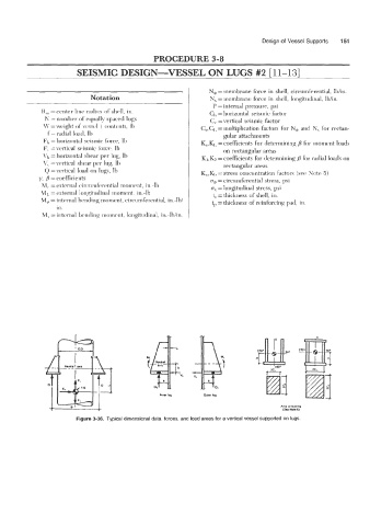
Figure 3-36. Typical dimensional data, forces, and load areas for a vertical vessel supported on lugs.