Page 168 - Pressure Vessel Design Manual
P. 168

146    Pressure Vessel Design Manual
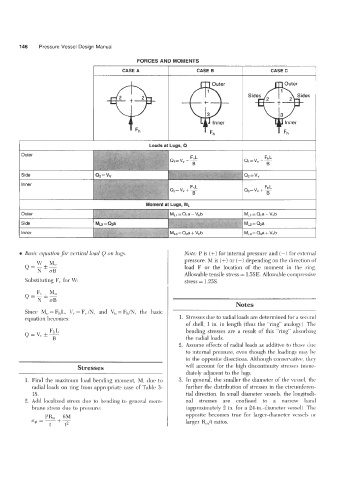
                                                 FORCES AND MOMENTS
                                            CASE A                    CASE B                    CASE C

                                                                           Outer                   7 Outer


                                                                            Inner                    Inner


        I                                            Loads at Lugs, Q


        0  Basic equation for vertical load  Q on 1t~g.s.         Note: P  is (+)  for internal pressure and (-)  for external
                                                                  pressure. M is (+)  or (-)  depending on the direction of
              w  Mo
          Q=Nhz                                                   load  F  or  the  location  of  the  moment  in  the  ring.
                                                                  Allowable tensile stress = 1.5SE. Allowable compressive
          Substituting F,  for W:                                 stress = 1.25s.
              Fv
          Q=-&-  M,
              N   OB
                                                                                    Notes
          Since  M,  = FhL,  v, = F,/N,  and  vh = Fh/N,  the  basic
          equation becomes:                                     1. Stresses due to radial loads are determined for a second
                                                                  of  shell,  1 in.  in length  (thus the “ring” analogy). The
                                                                  bending  stresses  are a  result  of  this  “ring” absorbing
                                                                  the radial loads.
                                                                2.  Assume effects of radial loads as additive to those due
                                                                  to internal pressure,  even though the loadings may be
                                                                  in the opposite directions. Although conservative, they
                            Stresses                              will  account for the high  discontinuity  stresses imme-
                                                                  diately adjacent to the lugs.
          1. Find the maximum load  bending  moment,  M,  due to   3.  In general,  the smaller the diameter  of the vessel,  the
            radial loads on ring from appropriate  case of Table 3-   further the distribution of stresses in the circumferen-
            18.                                                   tial direction. In small diameter vessels, the longitudi-
          2.  Add  localized  stress due to bending to general  mem-   nal  stresses  are  confined  to  a  narrow  band
            brane stress due to pressure:                         (approximately 2 in. for a 24-in.-diameter vessel). The
                       6M
                 PR,   +-                                         opposite  becomes  true  for  larger-diameter  vessels  or
            O@ =                                                  larger R,/t  ratios.
                  t     t2
                 ~
   163   164   165   166   167   168   169   170   171   172   173