
Page 166 - Pressure Vessel Design Manual
P. 166
B
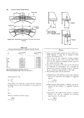
144 Pressure Vessel Design Manual
1-7~3
r
Load area
Ab
Load area b
Area of bearing =
area of cap plate
b = 0 = diameter of plate
Figure 3-28. Determining the thickness of the lower ring to resist Support
bending.
Table 3-15
Maximum Bending Moments in a Bearing Plate With Gussets
Notes
e
- 1. Rings may induce high localized stresses in shell imme-
b
diately adjacent to rings. For an analysis of these
stresses, see Procedure 4-3.
0 0 ( - )0.500Bp12 2. When l/b 5 1.5, the maximum bending moment
0.333 0.0078 B, b2 ( - )0.428~,e~ occurs at the junction of the ring and shell. When
0.5 0.0293 B, b2 ( - )0.319Bp12
0.666 0.0558 B, b2 ( - )0.227Bp12 l/b >1.5, the maximum bending moment occurs at
1 .o 0.0972 B, b2 (-)0.119Bp12 the middle of the free edge.
1.5 0.1230 B, b2 ( - )O. 1 24Bp12 3. Since the mean radius of the rings may be unknown at
2.0 0.1 31 0 B, b2 ( - )0.125BpE2 the beginning of computations, yet is required for
3.0-00 0.1330BP b2 ( - )0.125Bp12
determining maximum bending moment, substitute
Reprinted by permission of John Wiley & Sons, Inc. R, as a satisfactory approximation at that stage.
From Process Equipment Design, Table 10.3. (See Note 2.)
4. The following values may be estimated:
e Ring thickness: The thickness of each ring is arbitrary
Bearing pressure, B,: and can be selected by the designer. A suggested
value is
Q
BP =Ab
From Table 3-15, select the equation for the maximum
bending moment in the bearing plate. Use the greater of Ring spacing: Ring spacing is arbitrary and can be
M, or M,. selected by the designer. A suggested minimum
value is
c
_-
b- h=B-D
M1, = Ring depth: The depth of ring cannot be computed
directly, but must be computed by successive
Minimum thickness of lower ring, th: approximations. As a first trial,